INSTALLATION CAUTION / NOTICE / HINT CAUTION: As the rear bumper cover is extremely heavy, the engine lifter may suddenly drop if the instructions listed in the repair manual are not followed. Therefore, always follow the instructions listed in the repair manual when performing this procedure. PROCEDURE 1. INSTALL NO. 2 ULTRASONIC SENSOR (for Steel Type Bumper)
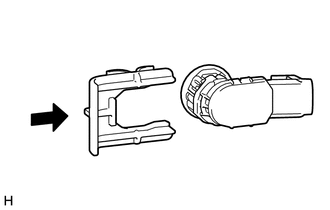
2. INSTALL NO. 2 ULTRASONIC SENSOR RETAINER (for Steel Type Bumper)
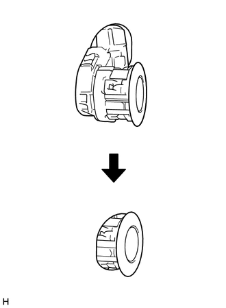
3. INSTALL NO. 2 ULTRASONIC SENSOR (for Resin Type Bumper) 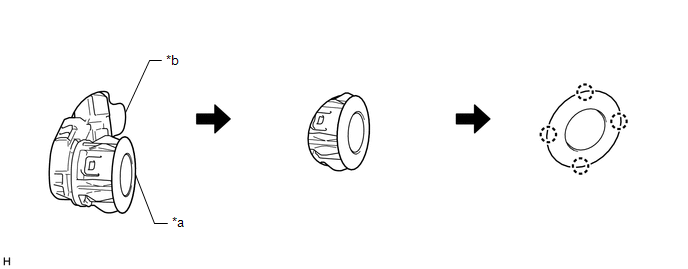 (a) Attach the 4 claws to install the No. 2 ultrasonic sensor as shown in the illustration. Text in Illustration
NOTICE:
4. INSTALL NO. 3 ULTRASONIC SENSOR (a) Attach the 4 claws to install the No. 3 ultrasonic sensor as shown in the illustration. Text in Illustration
NOTICE:
5. INSTALL NO. 2 FRAME WIRE (for Steel Type Bumper)
6. INSTALL REAR BUMPER BAR CORNER REINFORCEMENT LH (for Steel Type Bumper) 7. INSTALL REAR BUMPER BAR CORNER REINFORCEMENT RH (for Steel Type Bumper) 8. INSTALL REAR BUMPER EXTENSION INSERT LH (for Resin Type Bumper) 9. INSTALL REAR BUMPER EXTENSION INSERT RH (for Resin Type Bumper) 10. INSTALL LICENSE PLATE LIGHT ASSEMBLY LH 11. INSTALL LICENSE PLATE LIGHT ASSEMBLY RH HINT: Use the same procedure described for the LH side. 12. INSTALL REAR BUMPER PAD SUB-ASSEMBLY (for Steel Type Bumper) 13. INSTALL REAR BUMPER PAD SUB-ASSEMBLY (for Resin Type Bumper) 14. INSTALL REAR BUMPER PLATE LH (for Steel Type Bumper) 15. INSTALL REAR BUMPER PLATE LH (for Resin Type Bumper) 16. INSTALL REAR BUMPER PLATE RH (for Steel Type Bumper) 17. INSTALL REAR BUMPER PLATE RH (for Resin Type Bumper) 18. INSTALL REAR BUMPER COVER (for Steel Type Bumper) 19. INSTALL REAR BUMPER COVER (for Resin Type Bumper) 20. INSTALL WIRING HARNESS CONNECTOR (for Steel Type Bumper) 21. INSTALL WIRING HARNESS CONNECTOR (for Resin Type Bumper) 22. INSTALL CONNECTOR COVER (for Steel Type Bumper) 23. INSTALL CONNECTOR COVER (for Resin Type Bumper) |
Toyota Tundra Service Manual > Radio Receiver(for Column Shift Type): Installation
INSTALLATION PROCEDURE 1. INSTALL STEREO COMPONENT TUNER ASSEMBLY (w/ Satellite Radio) 2. INSTALL NO. 2 RADIO RECEIVER BRACKET (a) w/o Satellite Radio: Install the No. 2 radio receiver bracket with the 3 bolts. Torque: 3.5 N·m {36 kgf·cm, 31 in·lbf} (b) w/ Satellite Radio: Install the No. 2 radio ...