Toyota Tundra Service Manual: Components

COMPONENTS

ILLUSTRATION
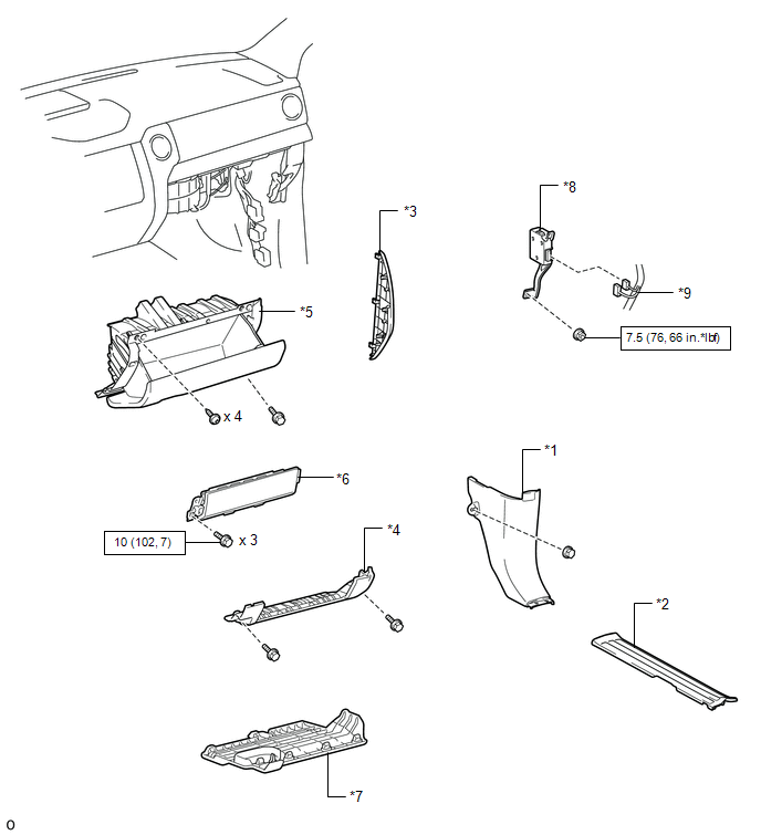
*1

COWL SIDE TRIM BOARD RH

*2

FRONT DOOR SCUFF PLATE RH

*3

INSTRUMENT SIDE PANEL RH

*4

LOWER INSTRUMENT PANEL

*5

LOWER INSTRUMENT PANEL FINISH PANEL SUB-ASSEMBLY RH

*6

LOWER NO. 2 INSTRUMENT PANEL AIRBAG ASSEMBLY

*7

NO. 2 INSTRUMENT PANEL UNDER COVER SUB-ASSEMBLY

*8

TRAILER BRAKE CONTROL ECU (BRAKE CONTROL WITH BRACKET RELAY)

*9

CONNECTOR

-

-

N*m (kgf*cm, ft.*lbf): Specified torque

-

-

    Trailer Brake Control Ecu

    Installation

    See More:

    Toyota Tundra Service Manual > Front Propeller Shaft Assembly: Disassembly
    DISASSEMBLY PROCEDURE 1. REMOVE FRONT PROPELLER SHAFT JOINT SPIDER BEARING SNAP RING (a) Place matchmarks on the flange yoke. Text in Illustration *a Matchmark (b) Using a brass bar and hammer, slightly tap in the spider bearing outer races. (c) Using needle-nose pliers, remove the 4 snap rings from ...

    Toyota Tundra Owners Manual

    Toyota Tundra Service Manual

    © 2026 Copyright www.ttundra.com
    0.0158