Toyota Tundra Service Manual: Installation

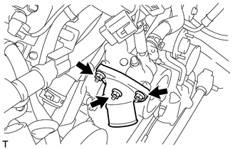
INSTALLATION

PROCEDURE

1. INSTALL WATER INLET SUB-ASSEMBLY WITH THERMOSTAT

(a) Install a new gasket and the water inlet with thermostat with the 3 nuts.

Torque:

10 N·m {102 kgf·cm, 7 ft·lbf}

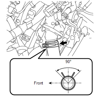
2. CONNECT OUTLET RADIATOR HOSE

(a) Connect the radiator hose.

HINT:

The direction of hose clamp is indicated in the illustration.

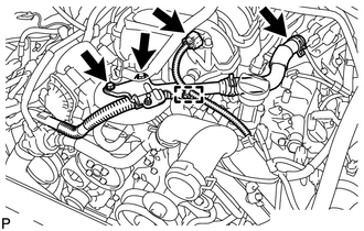
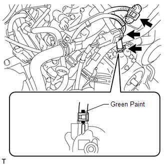
3. INSTALL AIR TUBE SUB-ASSEMBLY LH

(a) Connect the air hose to the air switching valve LH, and install the air tube LH with the 2 bolts.

Torque:

10 N·m {102 kgf·cm, 7 ft·lbf}

(b) Connect the vacuum sensor connector and clamp.

(c) Connect the air tube LH to the water inlet housing with the bolt.

Torque:

10 N·m {102 kgf·cm, 7 ft·lbf}

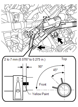
(d) Connect the air hose.

(e) Connect the 2 wire harness clamps.

HINT:

When installing the hose, make sure the paint mark and clip are as shown in the illustration.

(f) Connect the water by-pass hose and 2 connectors.

HINT:

When installing the hose, make sure the paint mark and clip are as shown in the illustration.

4. ADD ENGINE COOLANT

5. INSPECT FOR COOLANT LEAK

6. INSTALL AIR CLEANER ASSEMBLY

7. INSTALL V-BANK COVER SUB-ASSEMBLY

8. INSTALL NO. 1 ENGINE UNDER COVER

    Inspection

    Removal

    See More:

    Toyota Tundra Service Manual > Navigation System: Microphone Circuit between Microphone and Navigation Receiver Assembly
    DESCRIPTION This circuit sends a microphone signal from the telephone microphone assembly to the navigation receiver assembly. It also supplies power from the navigation receiver assembly to the telephone microphone assembly. WIRING DIAGRAM PROCEDURE 1. CHECK HARNESS AND CONNECTOR (NAVIGATION RECEIV ...

    Toyota Tundra Owners Manual

    Toyota Tundra Service Manual

    © 2024 Copyright www.ttundra.com
    0.0103