Components COMPONENTS ILLUSTRATION 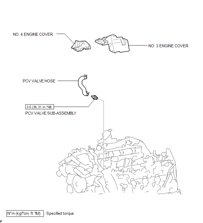 Inspection INSPECTION PROCEDURE 1. INSPECT PCV VALVE SUB-ASSEMBLY
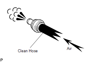
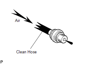
(b) Check the PCV valve sub-assembly operation. (1) Blow air into the cylinder head side, and check that air passes through easily. CAUTION: Do not suck air through the valve. Petroleum substances inside the valve are hazardous to your health.
(c) Remove the clean hose from the PCV valve sub-assembly. Installation INSTALLATION PROCEDURE 1. INSTALL PCV VALVE SUB-ASSEMBLY
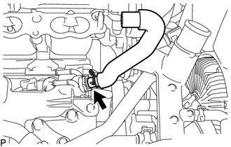
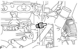
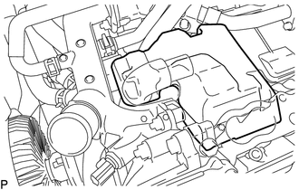
(b) Install the PCV valve sub-assembly. Torque: 3.5 N·m {36 kgf·cm, 31 in·lbf} 2. CONNECT PCV VALVE HOSE (a) Connect the PCV valve hose to the PCV valve sub-assembly, and slide the clamp to secure the hose. 3. INSTALL NO. 3 ENGINE COVER
4. INSTALL NO. 4 ENGINE COVER
5. INSTALL INTAKE MANIFOLD (See page Removal REMOVAL PROCEDURE 1. REMOVE INTAKE MANIFOLD (See page 2. REMOVE NO. 4 ENGINE COVER
3. REMOVE NO. 3 ENGINE COVER
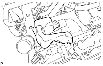
4. DISCONNECT PCV VALVE HOSE
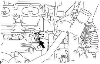
5. REMOVE PCV VALVE SUB-ASSEMBLY
|
Toyota Tundra Owners Manual > Bluetooth phone: Contact/Call History
Settings
The contact can be transferred from a Bluetooth phone to the system. The contact also can be added, edited and deleted. The call history can be deleted and contact and favorites can be changed. 1. Display the "Phone/Message Settings" screen. 2. Select "Contact/Call History Settings". 3. Select the d ...


 )
) )
)