Components COMPONENTS ILLUSTRATION 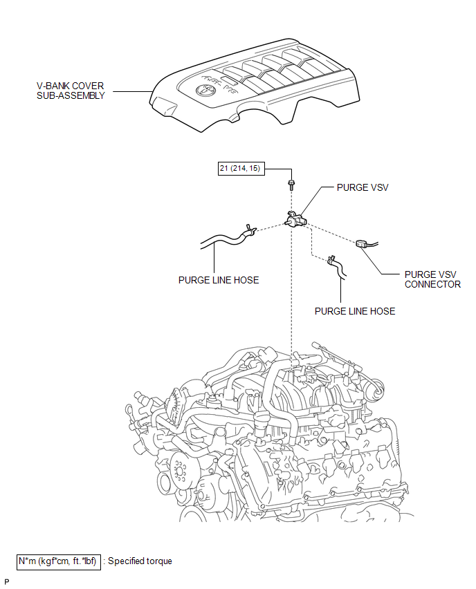 Inspection INSPECTION PROCEDURE 1. INSPECT PURGE VSV 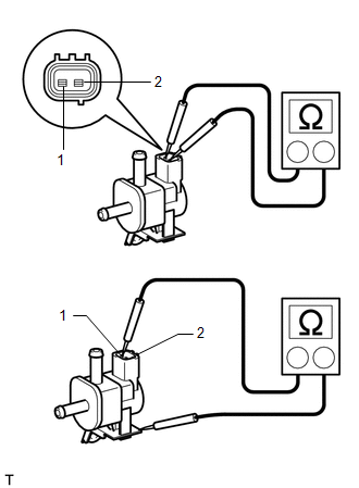 (a) Measure the resistance according to the value(s) in the table below. Standard Resistance:
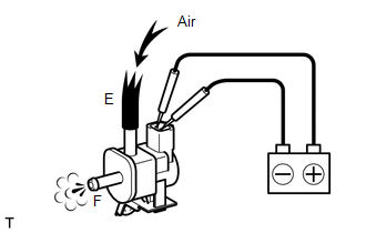
If the result is not as specified, replace the purge VSV. (b) Inspect the purge VSV operation. 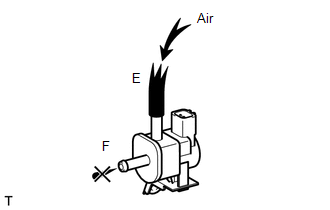 (1) Check that air does not flow from ports.
(3) Check that air flows from ports. If the result is not as specified, replace the purge VSV. Installation INSTALLATION PROCEDURE 1. INSTALL PURGE VSV
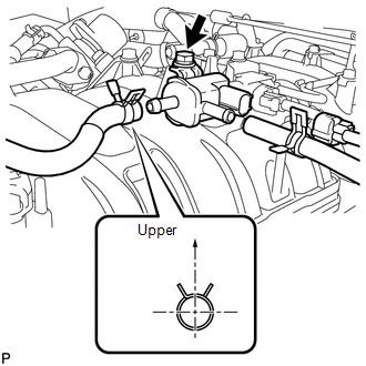
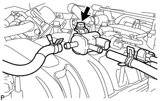
(b) Connect the connector. 2. CONNECT PURGE LINE HOSE (a) Connect the 2 hoses. HINT: Turn the claw of the clip to the upper side. 3. INSTALL V-BANK COVER SUB-ASSEMBLY Removal REMOVAL PROCEDURE 1. REMOVE V-BANK COVER SUB-ASSEMBLY 2. DISCONNECT PURGE LINE HOSE (a) Disconnect the 2 purge line hoses. 3. REMOVE PURGE VSV
(b) Remove the bolt and purge VSV. |
Toyota Tundra Service Manual > Power Window Regulator Motor(for Front Door): Inspection
INSPECTION PROCEDURE 1. INSPECT FRONT POWER WINDOW REGULATOR MOTOR ASSEMBLY LH (w/o Jam Protection Function) (a) Apply battery voltage to connector terminals 1 and 2. (b) Apply battery voltage to the regulator motor and check the operation of the front power window regulator motor assembly LH. OK: M ...