REMOVAL PROCEDURE 1. REMOVE V-BANK COVER SUB-ASSEMBLY 2. REMOVE AIR CLEANER HOSE ASSEMBLY 3. REMOVE CAMSHAFT TIMING OIL CONTROL VALVE ASSEMBLY (for Exhaust Side of Bank 1) 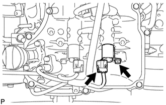 (a) Disconnect the oil control valve connector. (b) Remove the bolt and oil control valve. (c) Remove the O-ring from the oil control valve. 4. REMOVE CAMSHAFT TIMING OIL CONTROL VALVE ASSEMBLY (for Intake Side of Bank 1) 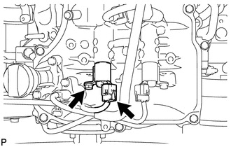 (a) Disconnect the oil control valve connector. (b) Remove the bolt and oil control valve. (c) Remove the O-ring from the oil control valve. 5. REMOVE CAMSHAFT TIMING OIL CONTROL VALVE ASSEMBLY (for Intake Side of Bank 2) 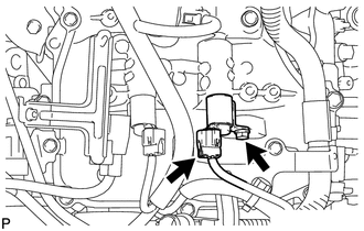 (a) Disconnect the oil control valve connector. (b) Remove the bolt and oil control valve. (c) Remove the O-ring from the oil control valve. 6. REMOVE CAMSHAFT TIMING OIL CONTROL VALVE ASSEMBLY (for Exhaust Side of Bank 2) 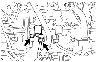 (a) Disconnect the oil control valve connector. (b) Remove the bolt and oil control valve. (c) Remove the O-ring from the oil control valve. |
Toyota Tundra Service Manual > Occupant Classification System: Front Occupant Classification Sensor LH Circuit Malfunction (B1780)
DESCRIPTION The front occupant detection sensor LH circuit consists of the occupant classification ECU and the front occupant detection sensor LH. DTC B1780 is set when a malfunction is detected in the front occupant detection sensor LH circuit. DTC Code DTC Detection Condition Trouble Area B1780 On ...


