Components COMPONENTS ILLUSTRATION 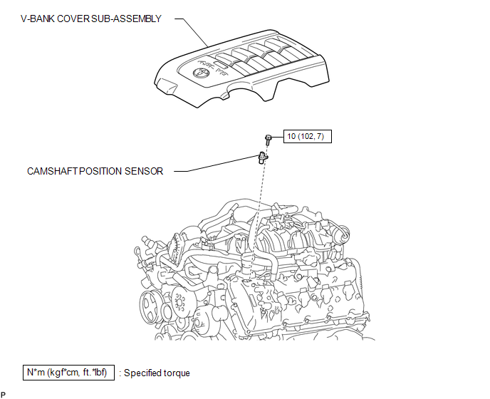 Installation INSTALLATION PROCEDURE 1. INSTALL CAMSHAFT POSITION SENSOR  (a) Install the sensor with the bolt. Torque: 10 N·m {102 kgf·cm, 7 ft·lbf} (b) Connect the sensor connector. 2. INSTALL V-BANK COVER SUB-ASSEMBLY Removal REMOVAL PROCEDURE 1. REMOVE V-BANK COVER SUB-ASSEMBLY 2. REMOVE CAMSHAFT POSITION SENSOR 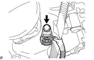 (a) Disconnect the sensor connector. (b) Remove the bolt and sensor. |
Toyota Tundra Service Manual > Room Temperature Sensor(for Automatic Air Conditioning System): Inspection
INSPECTION PROCEDURE 1. INSPECT COOLER (ROOM TEMPERATURE SENSOR) THERMISTOR (a) Measure the resistance according to the value(s) in the table below. Standard Resistance: Tester Connection Condition Specified Condition 1 - 2 10°C (50°F) 3.00 to 3.73 kΩ 15°C (59°F) 2.45 to 2.88 kΩ 20°C (68°F) ...


