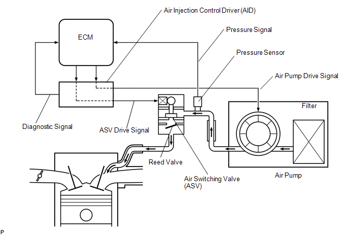
DESCRIPTION The Secondary
Air Injection (AIR) system consists of an air pump, the Air Switching
Valve (ASV), a pressure sensor, the Air Injection Control Driver (AID)
and the ECM. For a short time after a cold engine start, the AIR system
pumps secondary air to the exhaust port of the cylinder head to purify
the exhaust emissions. The secondary air is supplied by the air pump and
is pumped to the exhaust port through the ASV. The
AID drives the ASV and the air pump according to command signals
transmitted by the ECM. The pressure sensor detects the pressure in the
secondary air passage when the AIR system is ON and OFF, and transmits a
pressure signal to the ECM. The AID is not only
equipped to drive the pump and valve, but also has a diagnosis function
to detect malfunctions in the AIR system circuit. HINT: As a large current is required to drive the air pump and ASV, an AID is installed to this system.
 |
DTC No. | DTC Detection Condition |
Trouble Area | | P0412
P0415 |
- After cold engine start, all of following conditions met (1 trip detection logic):
- Secondary Air Injection (AIR) system not operating (air pump OFF, Air Switching Valve [ASV] OFF)
- Diagnostic signal from Air Injection Control Driver (AID) 40%
- Battery voltage 8 V or more
|
- Open in air switching valve circuit
- Air injection control driver
- Air switching valve assembly
- ECM
| | P0412
P0415 |
- After cold engine start, all of following conditions met (1 trip detection logic):
- Secondary Air Injection (AIR) system operating (air pump ON, Air Switching Valve [ASV] ON)
- Diagnostic signal from Air Injection Control Driver (AID) 40%
- Battery voltage 8 V or more
|
- Short between air switching valve circuit and body ground
- Air injection control driver
- Air switching valve assembly
- ECM
| MONITOR DESCRIPTION
The
Air Injection Control Driver (AID) detects open and short circuits
according to the voltages of the air pump terminal (VP) and the Air
Switching Valve (ASV) terminal (VV), and transmits diagnostic
information as a signal to the ECM. For a short time after a cold engine start, the ECM transmits command signals to the AID to drive the air pump and ASV.
The AID transmits an ASV malfunction signal to the ECM if either of the following conditions is met:
- The voltage at the AID terminal relating to the ASV is low despite the
AID receiving command signals from the ECM to drive the ASV.
- The voltage at the AID terminal relating to the ASV is high despite the
AID receiving no command signals from the ECM to drive the ASV.
The ECM stores the DTC based on diagnostic signals from the AID. MONITOR STRATEGY |
Related DTCs | P0412: Secondary air injection system air switching valve circuit range check (Bank 1)
P0415: Secondary air injection system air switching valve circuit range check (Bank 2) | |
Required Sensors/Components (Main) | Air injection control driver | |
Required Sensors/Components (Related) |
Air switching valve assembly | |
Frequency of Operation | Once per drive cycle | |
Duration | 3 seconds | |
MIL Operation | Immediate | |
Sequence of Operation | None | TYPICAL ENABLING CONDITIONS Case 1 |
Monitor runs whenever following DTCs not present |
None | | Secondary air injection pump |
Operating | | Secondary air injection switching valve |
Operating | | Battery voltage |
8 V or more | | Ignition switch |
ON | | Starter |
OFF | Case 2 |
Monitor runs whenever following DTCs not present |
None | | Secondary air injection pump |
Not operating | | Secondary air injection switching valve |
Not operating | | Battery voltage |
8 V or more | | Ignition switch |
ON | | Starter |
OFF | TYPICAL MALFUNCTION THRESHOLDS |
Diagnostic signal duty ratio from air injection control driver |
31% or more, and 48% or less | COMPONENT OPERATING RANGE |
Diagnostic signal duty ratio from air injection control driver |
70% or more, and 90% or less when secondary air injection system operating.
0% when secondary air injection system not operating. | CONFIRMATION DRIVING PATTERN
NOTICE:
- This Secondary Air Injection Check only allows technicians to operate the AIR system for a maximum of 5 seconds.
Furthermore, the check can only be performed up to 4
times per trip. If the test is repeated, intervals of at least 30
seconds are required between checks.
While AIR system operation using the Techstream is prohibited, the Techstream display indicates the prohibition (WAIT or ERROR).
If ERROR is displayed on the Techstream during the test, stop the engine for 10 minutes, and then try again.
- Performing the Secondary Air Injection Check repeatedly may cause damage
to the AIR system. If necessary, leave an interval of several minutes
between System Check operations to prevent the system from overheating.
- When performing the Secondary Air Injection Check operation after the
battery cable has been reconnected, wait for 7 minutes with the ignition
switch turned to ON or the engine running.
- Turn the ignition switch off when the Secondary Air Injection Check operation finishes.
- Start the engine and warm it up.
- Turn the ignition switch off.
- Connect the Techstream to the DLC3.
- Turn the ignition switch to ON.
- Turn the Techstream on.
- Clear DTCs (if set) (See page
 ). ).
- Turn the ignition switch off and wait for at least 30 seconds.
- Turn the ignition switch to ON and turn the Techstream on.
- Enter the following menus: Powertrain / Engine and ECT / Utility / Secondary air injection check / Automatic Mode.
- Start the engine after the Techstream initialization is finished.
- Perform the System Check operation by pressing ENTER (Next).
- Perform the following to confirm the AIR system pending codes: Press ENTER (Exit).
- Check for pending DTCs.
OK:
No pending DTC is output.
- After the "Secondary air injection check" is completed, check for All
Readiness by entering the following menus: Powertrain / Engine and ECT /
Utility / All Readiness.
- Input the DTC: P0412 or P0415.
- Check the DTC judgment result.
|
Tester Display |
Description |
|
NORMAL |
- DTC judgment completed
- System normal
|
|
ABNORMAL |
- DTC judgment completed
- System abnormal
|
|
INCOMPLETE |
- DTC judgment not completed
- Perform driving pattern after confirming DTC enabling conditions
|
|
N/A |
- Unable to perform DTC judgment
- Number of DTCs which do not fulfill DTC preconditions has reached ECU memory limit
|
HINT:
- If the judgment result shows NORMAL, the system is normal.
- If the judgment result shows ABNORMAL, the system has a malfunction.
- If the test result is INCOMPLETE or N/A and no pending DTC is output,
perform a universal trip and check for permanent DTCs (See page
).
HINT:
- If no permanent DTC is output, the system is normal.
- If a permanent DTC is output, the system is malfunctioning.
- Turn the ignition switch off.
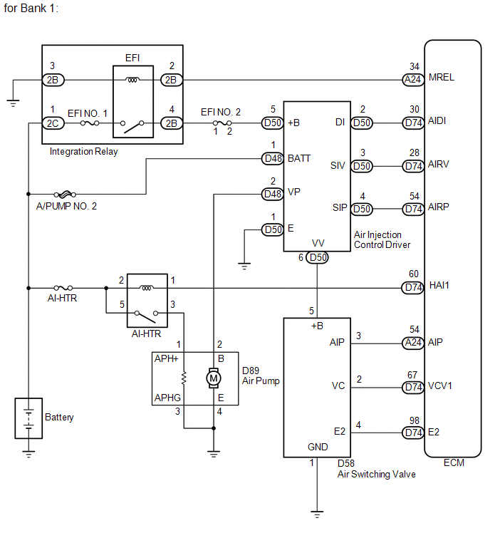
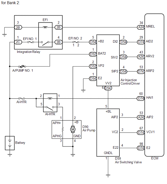
WIRING DIAGRAM
 CAUTION / NOTICE / HINT
HINT:
PROCEDURE |
1. | INSPECT AIR SWITCHING VALVE ASSEMBLY |
(a) Inspect the air switching valve (for bank 1) (See page
). (b) Inspect the air switching valve (for bank 2) (See page
). Result |
Result | Proceed to | |
OK | A | |
NG (for Bank 1) | B | |
NG (for Bank 2) | C |
| B |
 | REPLACE AIR SWITCHING VALVE ASSEMBLY (FOR BANK 1) |
| C |
| REPLACE AIR SWITCHING VALVE ASSEMBLY (FOR BANK 2) |
|
A |
 | |
| 2. |
CHECK HARNESS AND CONNECTOR (AIR SWITCHING VALVE - BODY GROUND) |
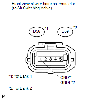 (a) Disconnect the air switching valve connector.
(b) Measure the resistance according to the value(s) in the table below.
Standard Resistance: |
Tester Connection | Condition |
Specified Condition | |
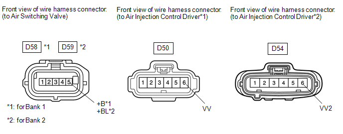
D58-1 (GND) - Body ground |
Always | Below 1 Ω | |
D59-1 (GNDL) - Body ground |
Always | Below 1 Ω |
| NG |
| REPAIR OR REPLACE HARNESS OR CONNECTOR |
|
OK | |
| |
| 3. |
CHECK HARNESS AND CONNECTOR (AIR SWITCHING VALVE - AIR INJECTION CONTROL DRIVER) |
 (a) Disconnect the air switching valve connector.
(b) Disconnect the air injection control driver connector. (c) Measure the resistance according to the value(s) in the table below.
Standard Resistance: |
Tester Connection | Condition |
Specified Condition | |
D58-5 (+B) - D50-6 (VV) |
Always | Below 1 Ω | |
D59-5 (+BL) - D54-6 (VV2) |
Always | Below 1 Ω | |
D58-5 (+B) or D50-6 (VV) - Body ground |
Always | 10 kΩ or higher | |
D59-5 (+BL) or D54-6 (VV2) - Body ground |
Always | 10 kΩ or higher |
| OK |
| REPLACE AIR INJECTION CONTROL DRIVER (FOR BANK 1 OR BANK 2) |
| NG |
| REPAIR OR REPLACE HARNESS OR CONNECTOR | |


