|
Terminal No. (Symbol) | Wiring Color |
Terminal Description | Condition |
Specified Condition |
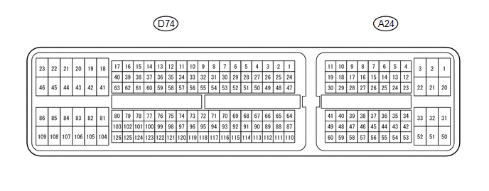
| A24-1 (BATT) - D74-81 (E1) |
L - BR | Battery (for measuring battery voltage and for ECM memory) |
Always | 11 to 14 V |
|
D74-41 (+BM) - D74-81 (E1) |
P - BR | Power source of throttle actuator |
Always | 11 to 14 V |
|
A24-28 (IGSW) - D74-81 (E1) |
LG - BR | Ignition switch |
Ignition switch ON | 11 to 14 V |
|
A24-3 (+B) - D74-81 (E1) |
GR - BR | Power source of ECM |
Ignition switch ON | 11 to 14 V |
|
A24-2 (+B2) - D74-81 (E1) |
GR - BR | Power source of ECM |
Ignition switch ON | 11 to 14 V |
|
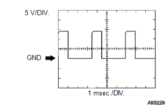
D74-58 (OC1+) - D74-57 (OC1-) |
B - B-L | Camshaft oil control valve (OCV) (for Intake Side of Bank 1) |
Idling | Pulse generation
(see waveform 1) |
| D74-52 (OC2+) - D74-51 (OC2-) |
L-B - R-B | Camshaft oil control valve (OCV) (for Intake Side of Bank 2) |
Idling | Pulse generation
(see waveform 1) |
| D74-56 (OE1+) - D74-55 (OE1-) |
L-W - L-B | Camshaft oil control valve (OCV) (for Exhaust Side of Bank 1) |
Idling | Pulse generation
(see waveform 1) |
| D74-50 (OE2+) - D74-49 (OE2-) |
L-R - L | Camshaft oil control valve (OCV) (for Exhaust Side of Bank 2) |
Idling | Pulse generation
(see waveform 1) |
| A24-34 (MREL) - D74-81 (E1) |
W - BR | EFI relay |
Ignition switch ON | 11 to 14 V |
|
D74-74 (VG) - D74-75 (E2G) |
L-Y - G-W | Mass air flow meter |
Idling, shift lever in P or N, A/C switch OFF |
0.5 to 3.0 V |
| D74-73 (THA) - D74-98 (E2) |
Y-B - BR | Intake air temperature sensor |
Idling, intake air temperature 20°C (68°F) |
0.5 to 3.4 V |
| D74-76 (THW) - D74-98 (E2) |
G-B - BR | Engine coolant temperature sensor |
Idling, engine coolant temperature 80°C (176°F) |
0.2 to 1.0 V |
| D74-80 (VCTA) - D74-79 (ETA) |
Y - L | Power source of throttle position sensor (specific voltage) |
Ignition switch ON | 4.5 to 5.5 V |
|
D74-78 (VTA1) - D74-79 (ETA) |
R-Y - L | Throttle position sensor (for engine control) |
Ignition switch ON, throttle valve fully closed |
0.5 to 1.1 V |
| Ignition switch ON,
throttle valve fully open |
3.2 to 4.8 V |
|
D74-77 (VTA2) - D74-79 (ETA) |
Y-B - L | Throttle position sensor (for sensor malfunction detection) |
Ignition switch ON, throttle valve fully closed |
2.1 to 3.1 V |
| Ignition switch ON,
throttle valve fully open |
4.6 to 5.0 V |
|
A24-55 (VPA) - A24-58 (EPA) |
W - BE | Accelerator pedal position sensor (for engine control) |
Ignition switch ON, accelerator pedal released |
0.5 to 1.1 V |
| Ignition switch ON,
accelerator pedal fully depressed |
2.6 to 4.5 V |
|
A24-56 (VPA2) - A24-60 (EPA2) |
LG - P | Accelerator pedal position sensor (for sensor malfunction detection) |
Ignition switch ON, accelerator pedal released |
1.2 to 2.0 V |
| Ignition switch ON,
accelerator pedal fully depressed |
4.7 to 4.75 V |
| A24-57 (VCPA) - A24-58 (EPA) |
B - BE | Power source of accelerator pedal position sensor (for VPA) |
Ignition switch ON | 4.5 to 5.5 V |
|
A24-59 (VCP2) - A24-60 (EPA2) |
V - P | Power source of accelerator pedal position sensor (for VPA2) |
Ignition switch ON | 4.5 to 5.5 V |
|
D74-22 (HA1A) - D74-23 (E04) |
L - W-B | A/F sensor heater |
Idling with warm engine |
Pulse generation (see waveform 2) |
|
D74-22 (HA1A) - D74-23 (E04) |
L - W-B | A/F sensor heater |
Ignition switch ON | 11 to 14 V |
|
D74-20 (HA2A) - D74-21 (E05) |
G - W-B | A/F sensor heater |
Idling with warm engine |
Pulse generation (see waveform 2) |
|
D74-20 (HA2A) - D74-21 (E05) |
G - W-B | A/F sensor heater |
Ignition switch ON | 11 to 14 V |
|
D74-126 (A1A+) - D74-81 (E1) |
G -BR | A/F sensor |
Ignition switch ON | 3.3 V*1 |
|
D74-125 (A1A-) - D74-81 (E1) |
R - BR | A/F sensor |
Ignition switch ON | 2.9 V*1 |
|
D74-103 (A2A+) - D74-81 (E1) |
P - BR | A/F sensor |
Ignition switch ON | 3.3 V*1 |
|
D74-102 (A2A-) - D74-81 (E1) |
L - BR | A/F sensor |
Ignition switch ON | 2.9 V*1 |
|
D74-45 (HT1B) - D74-46 (E03) |
G-B - W-B | Heated oxygen sensor heater |
Idling | Below 3.0 V |
|
D74-45 (HT1B) - D74-46 (E03) |
G-B - W-B | Heated oxygen sensor heater |
Ignition switch ON | 11 to 14 V |
|
D74-44 (HT2B) - D74-46 (E03) |
B - W-B | Heated oxygen sensor heater |
Idling | Below 3.0 V |
|
D74-44 (HT2B) - D74-46 (E03) |
B - W-B | Heated oxygen sensor heater |
Ignition switch ON | 11 to 14 V |
|
D74-114 (OX1B) - D74-115 (EX1B) |
G - L | Heated oxygen sensor |
Engine speed maintained at 2500 rpm for 2 minutes after warming up sensor |
Pulse generation (see waveform 3) |
|
D74-112 (OX2B) - D74-113 (EX2B) |
R - W |
| D74-86 (#10) - D74-43 (E01) |
R-L - W-B | Fuel injector assembly |
Ignition switch ON | 11 to 14 V |
|
D74-109 (#20) - D74-43 (E01) |
L - W-B | Idling |
Pulse generation (see waveform 4) |
|
D74-85 (#30) - D74-43 (E01) |
R - W-B |
| D74-108 (#40) - D74-43 (E01) |
Y - W-B |
| D74-84 (#50) - D74-43 (E01) |
G - W-B |
| D74-107 (#60) - D74-43 (E01) |
R - W-B |
| D74-83 (#70) - D74-43 (E01) |
W - W-B |
| D74-106 (#80) - D74-43 (E01) |
R-B - W-B |
| D74-94 (KNK1) - D74-93 (EKNK) |
R - G | Knock sensor |
Engine speed maintained at 4000 rpm after warming up engine |
Pulse generation (see waveform 5) |
|
D74-117 (KNK2) - D74-116 (EKN2) |
W - B |
| D74-96 (KNK3) - D74-95 (EKN3) |
W - B |
| D74-119 (KNK4) - D74-118 (EKN4) |
R - G |
| D74-92 (VV1+) - D74-91 (VV1-) |
R - G | Variable valve timing (VVT) sensor (for Intake Side of Bank 1) |
Idling | Pulse generation
(see waveform 6) |
| D74-87 (VV2+) - D74-88 (VV2-) |
R - Y | Variable valve timing (VVT) sensor (for Intake Side for Bank 2) |
Idling | Pulse generation
(see waveform 6) |
| D74-69 (EV1+) - D74-68 (EV1-) |
R-L - B | Variable valve timing (VVT) sensor (for Exhaust Side of Bank 1) |
Idling | Pulse generation
(see waveform 17) |
| D74-64 (EV2+) - D74-65 (EV2-) |
R-L - B | Variable valve timing (VVT) sensor (for Exhaust Side of Bank 2) |
Idling | Pulse generation
(see waveform 17) |
| D74-110 (NE+) - D74-111 (NE-) |
W - Y | Crankshaft position sensor |
Idling | Pulse generation
(see waveform 6) |
| D74-40 (IGT1) - D74-81 (E1) |
B-Y - BR | Ignition coil (ignition signal) |
Idling | Pulse generation
(see waveform 7) |
| D74-33 (IGT2) - D74-81 (E1) |
L-Y - BR |
| D74-37 (IGT3) - D74-81 (E1) |
B - BR |
| D74-34 (IGT4) - D74-81 (E1) |
L-B - BR |
| D74-35 (IGT5) - D74-81 (E1) |
G-R - BR |
| D74-36 (IGT6) - D74-81 (E1) |
G - BR |
| D74-38 (IGT7) - D74-81 (E1) |
G-W - BR |
| D74-39 (IGT8) - D74-81 (E1) |
G-B - BR |
| D74-104 (IGF1) - D74-81 (E1) |
G-B - BR | Ignition coil (ignition confirmation signal) |
Ignition switch ON | 4.5 to 5.5 V |
|
Idling | Pulse generation
(see waveform 7) |
|
D74-105 (IGF2) - D74-81 (E1) |
R - BR | Ignition coil (ignition confirmation signal) |
Ignition switch ON | 4.5 to 5.5 V |
|
Idling | Pulse generation
(see waveform 7) |
|
D74-63 (PRG) - D74-81 (E1) |
L-B - BR | Purge VSV |
Ignition switch ON | 11 to 14 V |
|
Idling | Pulse generation
(see waveform 8) |
| A24-13 (SPD) - D74-81 (E1) |
BE - BR | Speed signal from combination meter |
Driving at 20 km/h (12 mph) |
Pulse generation (see waveform 9) |
|
A24-46 (STA) - D74-81 (E1) |
R - BR | Starter signal |
Cranking | 5.5 V or more |
|
D74-120 (NSW) - D74-81 (E1) |
L - BR | Park/neutral position switch |
Ignition switch ON, shift lever position not in P or N |
11 to 14 V |
| Ignition switch ON, shift lever in P or N |
Below 3.0 V |
| A24-36 (STP) - D74-81 (E1) |
SB - BR | Stop light switch |
Brake pedal depressed |
7.5 to 14 V |
| Brake pedal released |
Below 1.5 V |
| A24-35 (ST1-) - D74-81 (E1) |
G - BR | Stop light switch
(opposite to STP terminal) | Ignition switch ON,
brake pedal depressed |
Below 1.5 V |
| Ignition switch ON,
brake pedal released |
7.5 to 14 V |
| D74-19 (M+) - D74-82 (ME01) |
R - W-B | Throttle actuator |
Idling with warm engine |
Pulse generation (see waveform 10) |
|
D74-18 (M-) - D74-82 (ME01) |
G - W-B | Throttle actuator |
Idling with warm engine |
Pulse generation (see waveform 11) |
|
A24-52 (FPC) - D74-81 (E1) |
B - BR | Fuel pump control |
Ignition switch ON | Below 1.5 V |
|
A24-16 (TC) - D74-81 (E1) |
Y - BR | Terminal TC of DLC3 |
Ignition switch ON | 11 to 14 V |
|
A24-15 (TACH) - D74-81 (E1) |
P - BR | Engine speed |
Idling | Pulse generation
(see waveform 12) |
| A24-30 (VPMP) - D74-81 (E1) |
V - BR | Vent valve (built into canister pump module) |
Ignition switch ON | 11 to 14 V |
|
A24-49 (MPMP) - D74-81 (E1) |
LG - BR | Leak detection pump (built into canister pump module) |
Leak detection pump OFF |
Below 3.0 V |
| Leak detection pump ON |
11 to 14 V |
| D74-67 (VCV1) - D74-98 (E2) |
L - BR | Power source for sensor (specific voltage) |
Ignition switch ON | 4.5 to 5.5 V |
|
D74-66 (VCV2) - D74-98 (E2) |
L - BR | Power source for sensor (specific voltage) |
Ignition switch ON | 4.5 to 5.5 V |
|
D74-121 (PPMP) - D74-98 (E2) |
P - BR | Canister pressure sensor (built into canister pump module) |
Ignition switch ON | 3.3 to 4.0 V |
|
D74-32 (ALT) - D74-81 (E1) |
R - BR | Generator |
Ignition switch ON | 11 to 14 V |
|
A24-10 (CANH) - D74-81 (E1) |
GR - BR | CAN communication line |
Ignition switch ON | Pulse generation
(see waveform 13) |
| A24-11 (CANL) - D74-81 (E1) |
W - BR | CAN communication line |
Ignition switch ON | Pulse generation
(see waveform 14) |
| D74-62 (ACIS) - D74-81 (E1) |
L-Y - BR | VSV for ACIS (Acoustic Control Induction System) operation signal |
Ignition switch ON | 11 to 14 V |
|
D74-60 (HAI1) - D74-81 (E1) |
B - BR | Air pump heater for secondary air injection system |
AI heater operating | Below 1.5 V |
|
D74-28 (AIRV) - D74-81 (E1) |
BR - BR | Air switching valve for secondary air injection system |
Ignition switch ON | 11 to 14 V |
|
D74-54 (AIRP) - D74-81 (E1) |
P - BR | Air pump control |
Ignition switch ON | 11 to 14 V |
|
D74-30 (AIDI) - D74-81 (E1) |
G - BR | Diagnostic information signal for secondary air injection system |
Secondary air injection system operating |
Pulse generation (see waveform 16) |
|
A24-54 (AIP) - D74-98 (E2) |
Y - BR | Secondary air injection system pressure signal |
Ignition switch ON | 3.0 to 3.6 V |
|
A24-43 (ARV2) - D74-81 (E1) |
V - BR | Air switching valve for secondary air injection system |
Ignition switch ON | 11 to 14 V |
|
D74-53 (ARP2) - D74-81 (E1) |
P-L - BR | Air pump control |
Ignition switch ON | 11 to 14 V |
|
D74-29 (AID2) - D74-81 (E1) |
G-Y - BR | Diagnostic information signal for secondary air injection system |
Air injection system operating |
Pulse generation (see waveform 16) |
|
A24-53 (AIP2) - D74-98 (E2) |
G - BR | Secondary air injection system pressure signal |
Ignition switch ON | 3.0 to 3.6 V |
|
D74-90 (G2) - D74- 89 (G2-) |
R - B | Camshaft position sensor |
Idling | Pulse generation
(see waveform 15) |
| A24-14 (STSW) - D74-81 (E1) |
BR - BR | Starter switch |
Shift lever in P or N, cranking |
6.0 V or more |
| A24-41 (ACCR) - D74-81 (E1) |
BR - BR | ACC relay control signal |
Ignition switch ON → Cranking |
11 to 14 V → Below 1 V |
|
D74-16 (STAR) - D74-81 (E1) |
L - BR | Starter relay control |
Ignition switch ON | Below 1.5 V |
|
Cranking | 5.5 V or more |
|
D74-72 (PSP) - D74-81 (E1) |
G - BR | Power steering oil pressure sensor |
Ignition switch ON | 0.5 to 4.5 V |
|
D74-97 (PIM) - D74-98 (E2) |
L-R - BR | Manifold absolute pressure sensor |
Idling | 1.2 to 2.0 V |
|
D74-48 (EGR1) - D74-81 (E1) |
B - BR | EGR valve assembly |
Engine racing with warm engine |
Pulse generation (see waveform 18) |
|
D74-1 (EGR2) - D74-81 (E1) |
B-L - BR | EGR valve assembly |
Engine racing with warm engine |
Pulse generation (see waveform 19) |
|
D74-24 (EGR3) - D74-81 (E1) |
B-R - BR | EGR valve assembly |
Engine racing with warm engine |
Pulse generation (see waveform 18) |
|
D74-47 (EGR4) - D74-81 (E1) |
B-Y - BR | EGR valve assembly |
Engine racing with warm engine |
Pulse generation (see waveform 19) |
|
A24-33 (ELS2) - D74-81 (E1) |
B - BR | Electric load |
Defogger switch on | 7.5 to 14 V |
|
Defogger switch off | Below 1.5 V |
|
A24-4 (ADJ1)*2 - Body ground |
W-B - Body ground | Vehicle type designation wire harness |
Always | Below 1 V |
 Camshaft Oil Control Valve (OCV)
 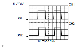 Air Fuel Ratio Sensor Heater
 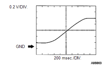 Heated Oxygen Sensor
 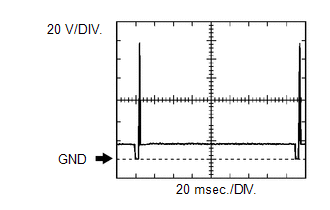 Fuel Injector No. 1 (to No. 8) Injection Signal
 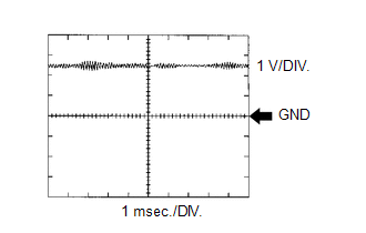 Knock Sensor
 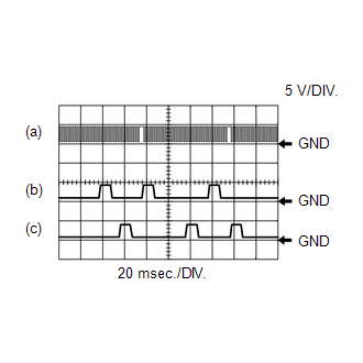 Crankshaft Position Sensor and VVT Sensor for Intake Side
 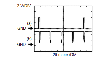 Igniter IGT Signal (from ECM to Igniter) and Igniter IGF Signal (from Igniter to ECM)
 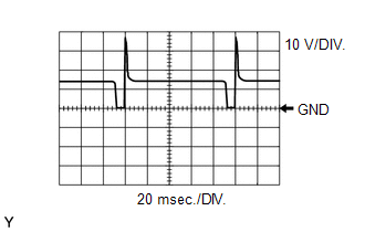 Purge VSV
 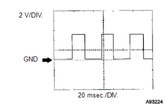 Vehicle Speed Signal
 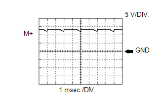 Throttle Actuator Positive Terminal
 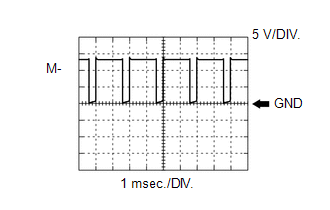 Throttle Actuator Negative Terminal
 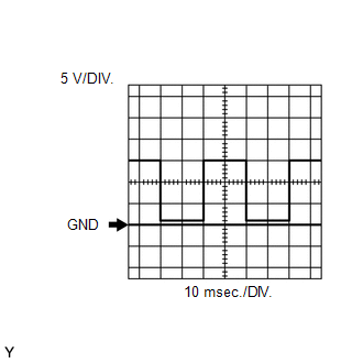 Engine Speed Signal
 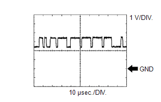 CAN Communication Signal (Reference)
 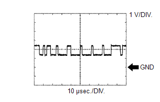 CAN Communication Signal (Reference)
 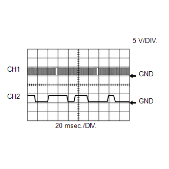 Crankshaft Position Sensor and Camshaft Position Sensor
 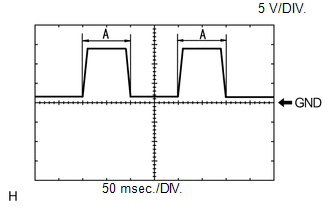 Terminal DI of Air Injection Control Driver
 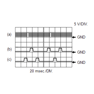 Crankshaft Position Sensor and VVT Sensor for Exhaust Side
 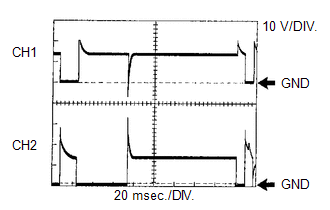 EGR Valve Signal
 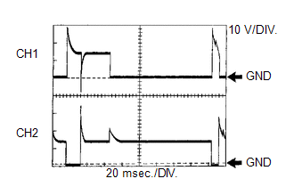 EGR Valve Signal
 ).
).
