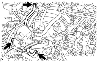
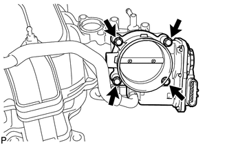
REMOVAL PROCEDURE 1. REMOVE NO. 1 ENGINE UNDER COVER 2. DRAIN ENGINE COOLANT 3. REMOVE V-BANK COVER SUB-ASSEMBLY 4. REMOVE AIR CLEANER HOSE ASSEMBLY 5. REMOVE THROTTLE BODY ASSEMBLY
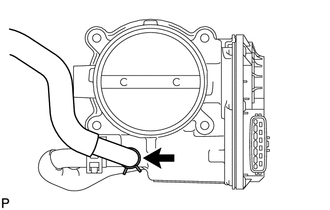
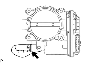
(b) Disconnect the throttle position sensor and control motor connector.
|
Toyota Tundra Service Manual > Front Differential Carrier Assembly(for 4wd): Installation
INSTALLATION PROCEDURE 1. INSTALL FRONT DIFFERENTIAL CARRIER ASSEMBLY (a) Install the differential support with the F and G bolts. Torque: 100 N·m {1020 kgf·cm, 74 ft·lbf} (b) Using a jack, slowly raise the front differential carrier assembly to its installation position. (c) Temporarily install ...