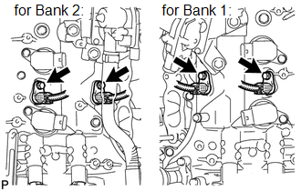
Components COMPONENTS ILLUSTRATION 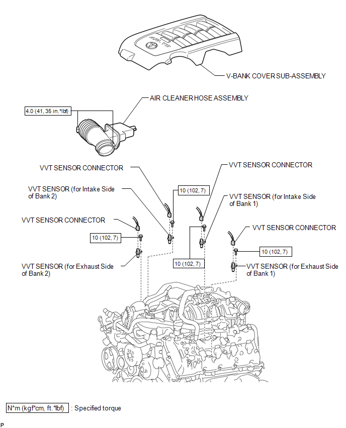 Installation INSTALLATION PROCEDURE 1. INSTALL VVT SENSOR
(b) Connect the 4 sensor connectors. 2. INSTALL AIR CLEANER HOSE ASSEMBLY 3. INSTALL V-BANK COVER SUB-ASSEMBLY Removal REMOVAL PROCEDURE 1. REMOVE V-BANK COVER SUB-ASSEMBLY 2. REMOVE AIR CLEANER HOSE ASSEMBLY 3. REMOVE VVT SENSOR
(b) Remove the 4 bolts and 4 sensors. |
Toyota Tundra Service Manual > Rear Seat Assembly(for Crewmax Rh Side): Removal
REMOVAL PROCEDURE 1. REMOVE REAR SEAT ASSEMBLY RH (a) Pull the No. 1 reclining adjuster release handle RH and fold up the seat cushion. (b) Remove the 4 bolts and rear seat assembly RH. NOTICE: Be careful not to damage the vehicle body. 2. REMOVE REAR SEAT INNER BELT ASSEMBLY HINT: Perform the follo ...