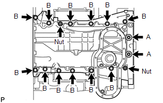
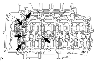
REASSEMBLY PROCEDURE 1. INSTALL STUD BOLT 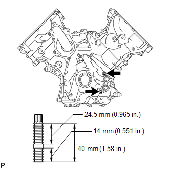 (a) Install the timing chain cover stud bolt. (1) Using an E10 "TORX" socket wrench, install the 2 stud bolts as shown in the illustration. Torque: 20 N·m {204 kgf·cm, 15 ft·lbf}
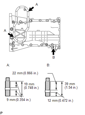
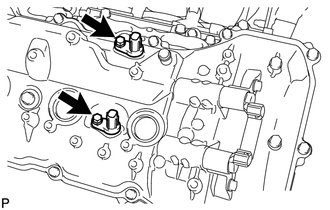
2. INSTALL RING PIN 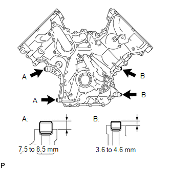 (a) Using a plastic-faced hammer, tap in new ring pins to the timing chain cover. Standard Protrusion:
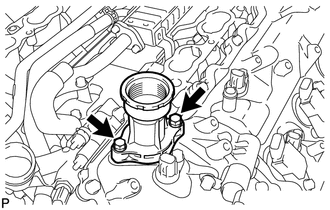
3. INSTALL REAR CRANKSHAFT OIL SEAL
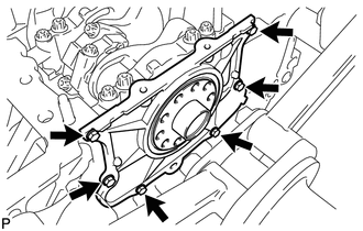
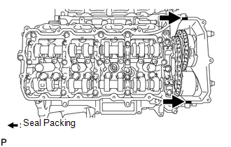
4. INSTALL OIL DRAIN PIPE SUB-ASSEMBLY 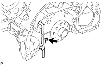 (a) Apply a light coat of engine oil to a new O-ring. (b) Install the O-ring to the drain pipe. (c) Install the oil drain pipe with the bolt. Torque: 10 N·m {102 kgf·cm, 7 ft·lbf} 5. INSTALL ENGINE REAR OIL SEAL RETAINER 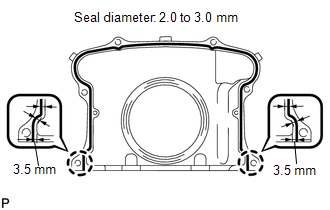 (a) Apply seal packing in a continuous line as shown in the illustration. Seal packing: Toyota Genuine Seal Packing Black, Three Bond 1207B or equivalent Seal diameter: 2.0 to 3.0 mm (0.0787 to 0.118 in.) Application position from inside edge of retainer: 3.5 mm (0.138 in.) NOTICE:
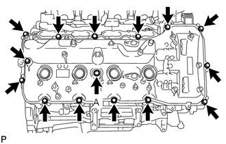
6. INSTALL OIL STRAINER SUB-ASSEMBLY 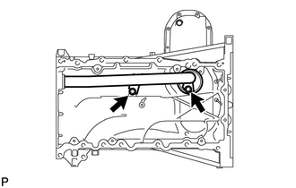 (a) Apply a light coat of engine oil to a new O-ring. (b) Install the O-ring to the oil strainer. (c) Install the oil strainer with the 2 bolts. Torque: 12 N·m {122 kgf·cm, 9 ft·lbf} NOTICE: Make sure the O-ring is not twisted or damaged. 7. INSTALL NO. 1 OIL PAN BAFFLE PLATE 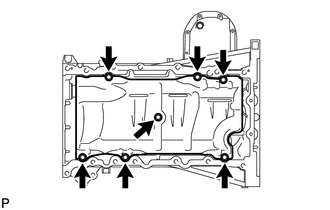 (a) Install the baffle plate with the 7 bolts. Torque: 12 N·m {122 kgf·cm, 9 ft·lbf} 8. INSTALL NO. 1 OIL PAN SUB-ASSEMBLY 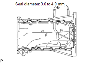 (a) Apply seal packing in a continuous line as shown in the illustration. Seal packing: Toyota Genuine Seal Packing Black, Three Bond 1207B or equivalent Standard seal diameter: 3.0 to 4.0 mm (0.118 to 0.157 in.) NOTICE:
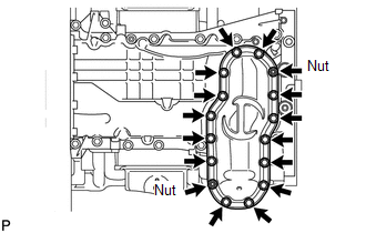
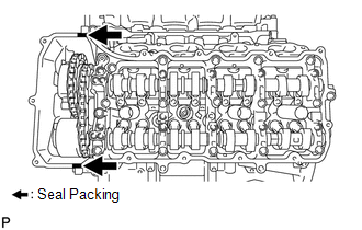
9. INSTALL NO. 2 OIL PAN SUB-ASSEMBLY 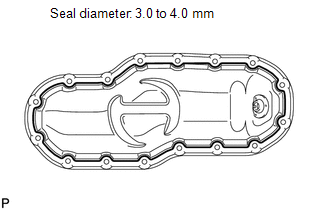 (a) Apply seal packing in a continuous line as shown in the illustration. Seal packing: Toyota Genuine Seal Packing Black, Three Bond 1207B or equivalent Standard seal diameter: 3.0 to 4.0 mm (0.118 to 0.156 in.) NOTICE:
10. INSTALL NO. 1 HEAT EXCHANGER COVER 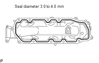 (a) Apply seal packing in a continuous line as shown in the illustration. Seal packing: Toyota Genuine Seal Packing 1282B, Three Bond 1282B or equivalent Standard seal diameter: 3.0 to 4.0 mm (0.118 to 0.157 in.) NOTICE:
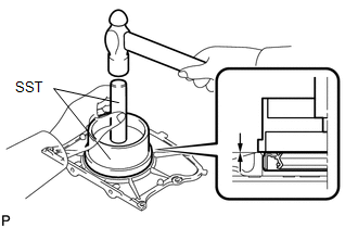
11. INSTALL VENTILATION PIPE GASKET 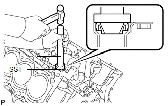 (a) Using SST, evenly tap in a new ventilation pipe gasket until its surface is flush with the lip of the ventilation pipe. SST: 09950-60010 09951-00360 SST: 09950-70010 09951-07100 NOTICE:
12. INSTALL OIL RETURN PIPE GASKET 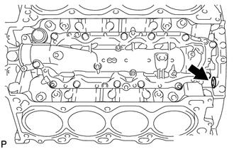 (a) Install a new oil return pipe gasket. 13. INSTALL CYLINDER BLOCK WATER JACKET SPACER 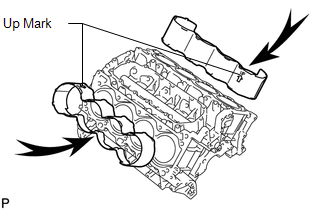 (a) Install the 2 water jacket spacers as shown in the illustration. NOTICE:
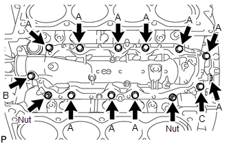
14. INSTALL CYLINDER HEAD GASKET RH
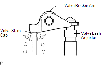
15. INSTALL CYLINDER HEAD GASKET LH 16. INSTALL CYLINDER HEAD SUB-ASSEMBLY RH 17. INSTALL CYLINDER HEAD SUB-ASSEMBLY LH 18. INSTALL VALVE STEM CAP (a) Apply a light coat of engine oil to the valve stem caps. (b) Install the 32 valve stem caps to the cylinder head. 19. INSTALL VALVE LASH ADJUSTER ASSEMBLY (a) Inspect the valve lash adjuster (See page (b) Install the 32 valve lash adjusters to the cylinder head. NOTICE: Install the lash adjuster at the same place it was removed from. 20. INSTALL NO. 1 VALVE ROCKER ARM SUB-ASSEMBLY (a) Apply engine oil to the lash adjuster tips and valve stem cap ends.
21. INSTALL CAMSHAFT BEARING CAP RH 22. INSTALL CAMSHAFT HOUSING SUB-ASSEMBLY RH
23. INSTALL CAMSHAFT BEARING CAP LH 24. INSTALL CAMSHAFT HOUSING SUB-ASSEMBLY LH 25. INSTALL CRANKSHAFT TIMING GEAR KEY 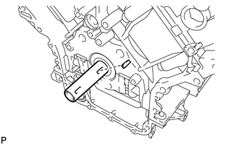 (a) Install the timing gear key. HINT: The other timing gear key will be installed at a later step. 26. INSTALL NO. 2 CHAIN TENSIONER ASSEMBLY
27. INSTALL NO. 1 CHAIN SUB-ASSEMBLY RH 28. INSTALL NO. 1 CHAIN VIBRATION DAMPER RH 29. INSTALL NO. 1 CHAIN TENSIONER SLIPPER RH 30. INSTALL NO. 1 CHAIN TENSIONER ASSEMBLY RH 31. INSTALL NO. 3 CHAIN TENSIONER ASSEMBLY 32. INSTALL NO. 1 CHAIN SUB-ASSEMBLY LH 33. INSTALL NO. 1 CHAIN TENSIONER SLIPPER LH 34. INSTALL NO. 1 CHAIN TENSIONER ASSEMBLY LH 35. INSTALL NO. 1 CHAIN VIBRATION DAMPER LH 36. TIGHTEN CAMSHAFT TIMING GEAR 37. CHECK NO. 1 CYLINDER TO TDC / COMPRESSION (a) Temporarily install the pulley set bolt. (b) Rotate the crankshaft clockwise, and check that the timing marks on the crankshaft timing gear and camshaft timing gears are as shown in the illustration. (c) Remove the crankshaft pulley set bolt. 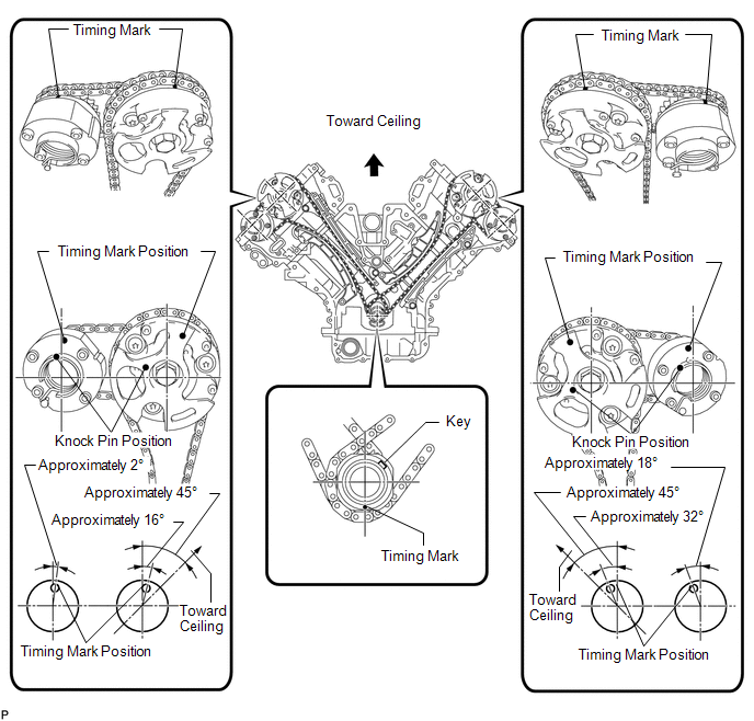 38. INSTALL WATER INLET PIPE 39. INSTALL TIMING CHAIN COVER SUB-ASSEMBLY 40. INSTALL WATER PUMP ASSEMBLY 41. INSTALL FRONT CRANKSHAFT OIL SEAL
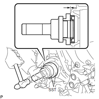
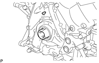
(b) Using SST and a hammer, tap in the oil seal to a depth between 0 to 1.0 mm (0 to 0.0394 in.) from the timing chain cover edge. SST: 09223-22010 SST: 09506-35010 NOTICE:
42. INSTALL CRANKSHAFT TIMING GEAR KEY
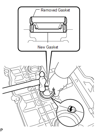
43. INSTALL SPARK PLUG TUBE GASKET 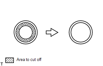 (a) Using a cutter knife, cut off the seal part of the removed gasket.
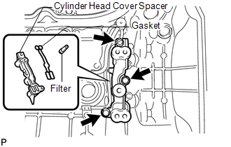
(c) Apply a light coat of MP grease to the gasket lip. (d) Return the 4 ventilation baffle plate claws to the original positions. 44. INSTALL OIL CONTROL VALVE FILTER 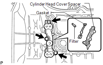 (a) LH: (1) Install the valve filter in the cylinder head cover. (2) Install a new gasket and the cylinder head cover spacer with the 3 bolts. Torque: 10 N·m {102 kgf·cm, 7 ft·lbf}
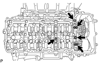
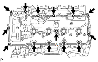
45. INSTALL CYLINDER HEAD COVER SUB-ASSEMBLY RH
(b) Install the cover gasket to the cylinder head cover. NOTICE: Remove any oil from the contact surface.
46. INSTALL CYLINDER HEAD COVER SUB-ASSEMBLY LH
(b) Install the cover gasket to the cylinder head cover. NOTICE: Remove any oil from the contact surface.
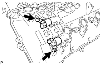
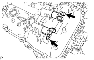
47. INSTALL CAMSHAFT OIL CONTROL VALVE ASSEMBLY
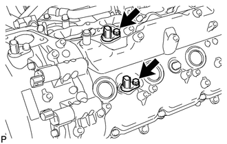
48. INSTALL CRANKSHAFT POSITION SENSOR 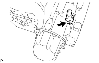 (a) Install the crankshaft position sensor with the bolt. Torque: 10 N·m {102 kgf·cm, 7 ft·lbf} 49. INSTALL CRANKSHAFT POSITION SENSOR PROTECTOR 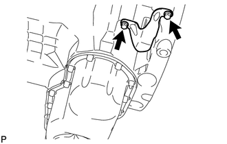 (a) Install the sensor protector with the 2 bolts. Torque: 10 N·m {102 kgf·cm, 7 ft·lbf} 50. INSTALL CAMSHAFT POSITION SENSOR 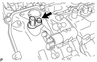 (a) Install the camshaft position sensor with the bolt. Torque: 10 N·m {102 kgf·cm, 7 ft·lbf} 51. INSTALL VVT SENSOR
52. INSTALL SPARK PLUG (a) Using a 16 mm plug wrench, install the 8 spark plugs. Torque: 21 N·m {214 kgf·cm, 15 ft·lbf} 53. INSTALL OIL FILLER CAP HOUSING
54. INSTALL OIL FILLER CAP SUB-ASSEMBLY 55. INSTALL CRANKSHAFT PULLEY 56. INSTALL OIL FILTER BRACKET 57. INSTALL OIL FILTER ELEMENT |
Toyota Tundra Service Manual > Rear Seat Assembly(for Double Cab): Reassembly
REASSEMBLY CAUTION / NOTICE / HINT CAUTION: Wear protective gloves. Sharp areas on the parts may injure your hands. PROCEDURE 1. INSTALL SEPARATE TYPE REAR SEATBACK COVER RH (a) Set the separate type rear seatback cover RH in place. (b) Using hog ring pliers, install the separate type rear seatback ...