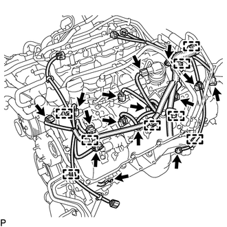
REMOVAL PROCEDURE 1. REMOVE ENGINE WIRE (a) Engine LH Side:
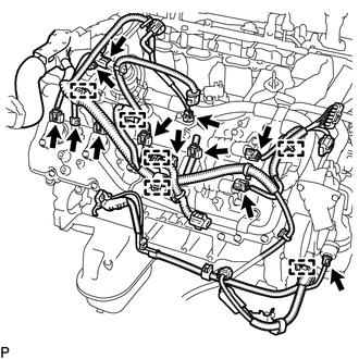
(2) Disconnect the 4 ignition coil connectors. (3) Disconnect the 2 VVT sensor connectors. (4) Disconnect the camshaft position sensor connector. (5) Disconnect the crankshaft position sensor connector. (6) Disconnect the air switching valve connector. (7) Disconnect the engine coolant temperature sensor connector. (8) Disconnect the fuel injector connector. (9) Disconnect the noise filter connector. (10) Remove the bolt and disconnect the 8 clamps. (b) Engine RH Side:
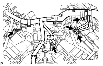
(2) Disconnect the 4 ignition coil connectors. (3) Disconnect the 2 VVT sensor connectors. (4) Disconnect the fuel injector connector. (5) Disconnect the noise filter connector. (6) Disconnect the air switching valve connector. (7) Disconnect the oil pressure sender gauge connector. (8) Disconnect the 6 clamps. (c) Engine Rear Side:
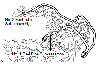
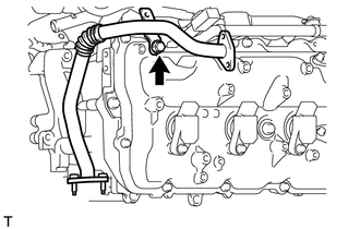
(2) Remove the 4 bolts. (d) Remove the engine wire. 2. REMOVE NO. 1 FUEL PIPE SUB-ASSEMBLY
3. REMOVE NO. 2 FUEL TUBE SUB-ASSEMBLY (a) Remove the No. 2 fuel tube (See page
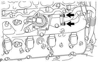
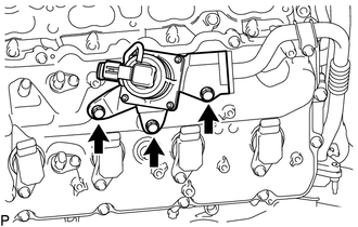
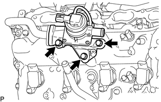
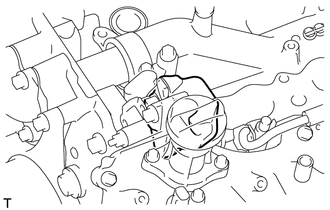
4. REMOVE AIR SWITCHING VALVE ASSEMBLY (for Bank 1)
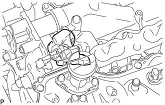
5. REMOVE AIR SWITCHING VALVE ASSEMBLY (for Bank 2)
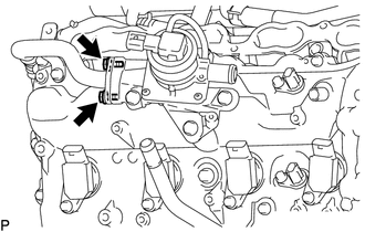
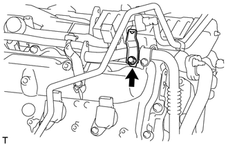
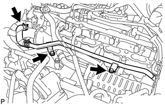
6. REMOVE NO. 4 AIR TUBE
7. REMOVE NO. 3 AIR TUBE
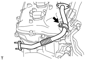
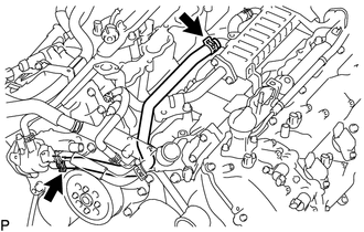
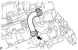
8. REMOVE NO. 3 WATER BY-PASS PIPE SUB-ASSEMBLY
9. REMOVE NO. 8 WATER BY-PASS HOSE
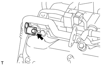
10. DISCONNECT NO. 11 WATER BY-PASS HOSE
11. REMOVE EGR COOLER ASSEMBLY
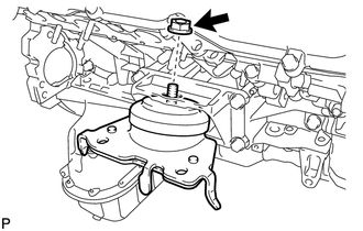
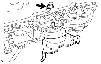
12. REMOVE CYLINDER BLOCK WATER DRAIN COCK SUB-ASSEMBLY 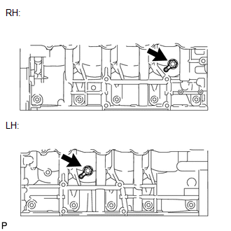 (a) Remove the 2 water drain cock plugs from the water drain cocks. (b) Remove the 2 water drain cocks from the cylinder block. 13. REMOVE FRONT ENGINE MOUNTING INSULATOR RH
14. REMOVE FRONT ENGINE MOUNTING INSULATOR LH
15. REMOVE FRONT NO. 1 ENGINE MOUNTING BRACKET RH 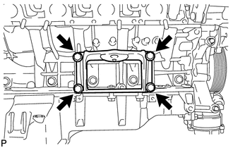 (a) Remove the 4 bolts and mounting bracket. 16. REMOVE FRONT NO. 1 ENGINE MOUNTING BRACKET LH 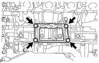 (a) Remove the 4 bolts and mounting bracket. 17. REMOVE FUEL DELIVERY PIPE SUB-ASSEMBLY LH
18. REMOVE FUEL DELIVERY PIPE SUB-ASSEMBLY RH 19. REMOVE OIL PRESSURE SENDER GAUGE ASSEMBLY 20. REMOVE NO. 4 ENGINE COVER 21. REMOVE NO. 3 ENGINE COVER 22. REMOVE NO. 1 WATER BY-PASS HOSE 23. REMOVE AIR TUBE SUB-ASSEMBLY RH 24. REMOVE WATER BY-PASS PIPE SUB-ASSEMBLY 25. REMOVE WATER INLET HOUSING 26. REMOVE FRONT WATER BY-PASS JOINT 27. REMOVE WATER PUMP PULLEY
28. REMOVE NO. 1 IDLER PULLEY SUB-ASSEMBLY 29. REMOVE FAN BRACKET SUB-ASSEMBLY 30. REMOVE V-RIBBED BELT TENSIONER ASSEMBLY 31. REMOVE SEPARATOR CASE
32. REMOVE NO. 2 ENGINE COVER
33. REMOVE NO. 1 ENGINE COVER
34. REMOVE ENGINE WIRE 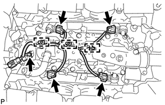 (a) Disconnect the 4 knock sensor connectors. (b) Disconnect the 3 clamps. Then remove the engine wire. 35. REMOVE NO. 11 WATER BY-PASS HOSE
36. REMOVE KNOCK SENSOR 37. REMOVE IGNITION COIL ASSEMBLY (a) Remove the 8 bolts and 8 ignition coils. 38. REMOVE NOISE FILTER (a) LH Side: Remove the bolt and noise filter from the cylinder head cover. (b) RH Side: Remove the bolt and noise filter from the cylinder head cover. |
Toyota Tundra Service Manual > Lighting System: Door Courtesy Switch Circuit
DESCRIPTION The main body ECU (multiplex network body ECU) detects the condition of the door courtesy light switch assembly. WIRING DIAGRAM PROCEDURE 1. READ VALUE USING TECHSTREAM (a) Using the Techstream, read the Data List. Click here Main Body Tester Display Measurement Item / Range Normal Condi ...

 ).
).