Toyota Tundra Service Manual: Installation

INSTALLATION

CAUTION / NOTICE / HINT

HINT:

If an exhaust gas leak has been repaired, perform an inspection following the repair (See page ).

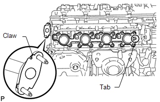
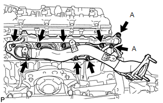
PROCEDURE

1. INSTALL EXHAUST MANIFOLD SUB-ASSEMBLY RH

(a) Install a new gasket to the cylinder head and a new gasket to the No. 3 air tube.

HINT:

  • Install the exhaust manifold gasket with the gasket tab facing toward the front of the engine.
  • Install the air tube gasket with the gasket's claws facing the tube.

(b) Temporarily install the exhaust manifold with 9 new nuts, and then uniformly tighten the 7 nuts that are not labeled A. Then tighten the 2 nuts labeled A in the illustration.

Torque:

for nut A :

10 N·m {102 kgf·cm, 7 ft·lbf}

except nut A :

21 N·m {214 kgf·cm, 15 ft·lbf}

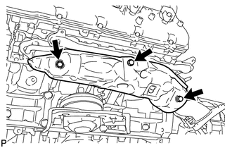
2. INSTALL NO. 1 EXHAUST MANIFOLD HEAT INSULATOR

(a) Install the heat insulator with the 3 bolts.

Torque:

10 N·m {102 kgf·cm, 7 ft·lbf}

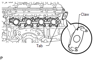
3. INSTALL EXHAUST MANIFOLD SUB-ASSEMBLY LH

(a) Install a new gasket to the cylinder head and a new gasket to the No. 4 air tube.

HINT:

  • Install the exhaust manifold gasket with the gasket tab facing toward the rear of the engine.
  • Install the air tube gasket with the gasket's claws facing the tube.

(b) Temporarily install the exhaust manifold with 9 new nuts, and then uniformly tighten the 7 nuts that are not labeled A. Then tighten the 2 nuts labeled A in the illustration.

Torque:

for nut A :

10 N·m {102 kgf·cm, 7 ft·lbf}

except nut A :

21 N·m {214 kgf·cm, 15 ft·lbf}

4. INSTALL NO. 2 EXHAUST MANIFOLD HEAT INSULATOR

(a) Install the heat insulator with the 3 bolts.

Torque:

10 N·m {102 kgf·cm, 7 ft·lbf}

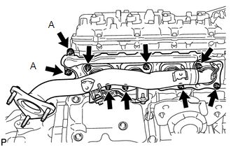
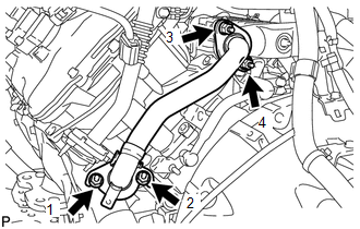
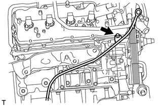
5. INSTALL NO. 1 EGR PIPE SUB-ASSEMBLY

(a) Install 2 new gaskets.

(b) Install the EGR pipe with the 4 nuts, and tighten the nuts in the sequence shown in the illustration.

Torque:

21 N·m {214 kgf·cm, 15 ft·lbf}

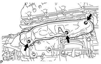
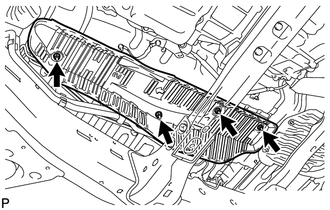
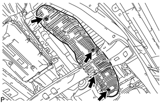
6. INSTALL FRONT NO. 3 FLOOR HEAT INSULATOR

(a) Install the front floor heat insulator with the 4 bolts.

Torque:

5.5 N·m {56 kgf·cm, 49 in·lbf}

7. INSTALL FRONT NO. 4 FLOOR HEAT INSULATOR

(a) Install the front floor heat insulator with the 4 bolts.

Torque:

5.5 N·m {56 kgf·cm, 49 in·lbf}

8. INSTALL FRONT PROPELLER SHAFT ASSEMBLY (for 4WD)

(See page )

9. INSTALL EXHAUST PIPE ASSEMBLY

(See page )

10. CONNECT COOLER COMPRESSOR ASSEMBLY

11. INSTALL GENERATOR ASSEMBLY

(See page )

12. INSTALL ENGINE OIL LEVEL DIPSTICK GUIDE

(a) Apply a light coat of engine oil to a new O-ring.

(b) Install the O-ring to the dipstick guide.

(c) Install the dipstick guide with the bolt.

Torque:

10 N·m {102 kgf·cm, 7 ft·lbf}

(d) Install the dipstick.

13. INSTALL INTAKE MANIFOLD

(See page )

14. INSPECT FOR EXHAUST GAS LEAK

HINT:

If an exhaust gas leak has been repaired, perform an inspection following the repair (See page ).

If gas is leaking, tighten the areas necessary to stop the leak. Replace damaged parts as necessary.

15. INSTALL FRONT FENDER APRON SEAL REAR LH

(a) Install the fender apron seal with the 5 clips.

16. INSTALL FRONT FENDER APRON SEAL LH

(a) Install the fender apron seal with the 6 clips.

17. INSTALL FRONT FENDER APRON SEAL REAR RH

(a) Install the fender apron seal with the 5 clips.

18. INSTALL FRONT FENDER APRON SEAL RH

(a) Install the fender apron seal with the 6 clips.

    Components

    Removal

    See More:

    Toyota Tundra Service Manual > Trailer Brake Control System: Power Supply Voltage Circuit (C1241)
    DESCRIPTION If a malfunction is detected in the power supply circuit, the trailer brake control ECU (brake control with bracket relay) stores this DTC. DTC No. Detection Item INF Code DTC Detection Condition Trouble Area C1241 Power Supply Voltage Circuit 81 82 INF Code: 81 (Low power supply voltage ...

    Toyota Tundra Owners Manual

    Toyota Tundra Service Manual

    © 2024 Copyright www.ttundra.com
    0.0108