REASSEMBLY PROCEDURE 1. INSTALL NO. 1 MONOLITHIC CONVERTER PROTECTOR (for Bank 2) (a) Install the 4 No. 1 converter protector stays to the front exhaust pipe assembly. (b) Install the lower No. 1 monolithic converter protector and upper No. 1 monolithic converter protector with the 4 bolts and 4 nuts. Torque: 11 N·m {107 kgf·cm, 8 ft·lbf} HINT: Install the No. 1 monolithic converter protector within the angle range specified in the illustration. 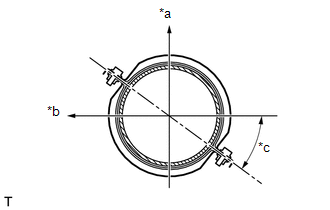 Text in Illustration Text in Illustration
2. INSTALL MONOLITHIC CONVERTER PROTECTOR (for Bank 2) (a) Install the 2 No. 1 converter protector stays and 2 No. 2 converter protector stays to the front exhaust pipe assembly. (b) Install the lower monolithic converter protector and upper monolithic converter protector with the 4 bolts and 4 nuts. Torque: 11 N·m {107 kgf·cm, 8 ft·lbf} HINT: Install the monolithic converter protector within the angle range specified in the illustration. 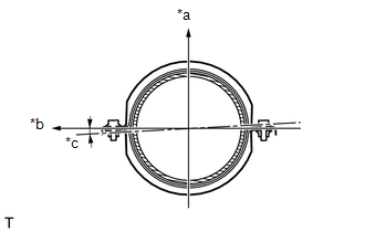 Text in Illustration Text in Illustration
3. INSTALL NO. 1 MONOLITHIC CONVERTER PROTECTOR (for Bank 1) (a) Install the 4 No. 1 converter protector stays to the front No. 2 exhaust pipe assembly. (b) Install the lower No. 1 monolithic converter protector and upper No. 1 monolithic converter protector with the 4 bolts and 4 nuts. Torque: 11 N·m {107 kgf·cm, 8 ft·lbf} HINT: Install the No. 1 monolithic converter protector within the angle range specified in the illustration. 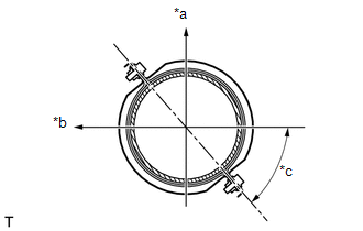 Text in Illustration Text in Illustration
4. INSTALL MONOLITHIC CONVERTER PROTECTOR (for Bank 1) (a) Install the 2 No. 1 converter protector stays and 2 No. 2 converter protector stays to the front No. 2 exhaust pipe assembly. (b) Install the lower monolithic converter protector and upper monolithic converter protector with the 4 bolts and 4 nuts. Torque: 11 N·m {107 kgf·cm, 8 ft·lbf} HINT: Install the monolithic converter protector within the angle range specified in the illustration. 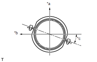 Text in Illustration Text in Illustration
|
Toyota Tundra Service Manual > Sfi System: A/F Sensor Slow Response - Rich to Lean Bank 1 Sensor 1 (P014C-P014F,P015A-P015D)
DESCRIPTION HINT: Refer to DTC P2195 (See page ). DTC No. DTC Detection Condition Trouble Area P014C The "Rich to Lean response rate deterioration level*" value is less than the standard. (2 trip detection logic) Air fuel ratio sensor (for bank 1 sensor 1) Air fuel ratio sensor (for bank 1 sensor 1) ...


