REMOVAL PROCEDURE 1. REMOVE FUEL TANK ASSEMBLY
Click here  2. REMOVE FUEL SUCTION WITH PUMP AND GAUGE TUBE ASSEMBLY
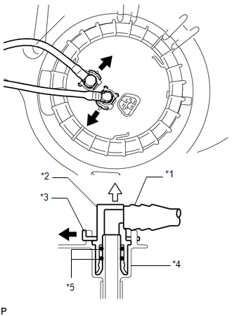
| (a) Remove the 2 tube joint clips and pull out the 2 fuel tank tubes.
NOTICE:
- Remove any dirt and foreign matter on the fuel tube joint before performing this work.
- Do not allow any scratches or foreign matter on the parts when
disconnecting them, as the fuel tube joint contains the O-rings that
seal the plug.
- Perform this work by hand. Do not use any tools.
- Do not forcibly bend, twist or turn the nylon tube.
- Protect the disconnected part by covering it with a plastic bag and tape after disconnecting the fuel tubes.
|
 |
|
*1 | Fuel Tank Tube | |
*2 | Tube Joint | |
*3 | Tube Joint Clip | |
*4 | Fuel Suction Plate | |
*5 | O-Ring | | |
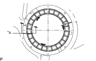
| (b) Apply a co-rotation prevention check mark to the fuel suction with pump and gauge tube assembly and fuel tank assembly.
NOTICE:
- The fuel tank assembly cutout is attached to the protrusion on the fuel tank vent tube assembly.
- If the fuel suction with pump and gauge tube assembly and fuel tank
assembly are not firmly attached and the fuel pump gauge retainer is
rotated, the fuel suction with pump and gauge tube assembly will
co-rotate and result in the fuel suction with pump and gauge tube
assembly being damaged.
- Make sure to apply a co-rotation prevention check mark to prevent the
fuel suction with pump and gauge tube assembly from co-rotating.
|
 |
|
*a | Co-rotation Prevention Check Mark | | |
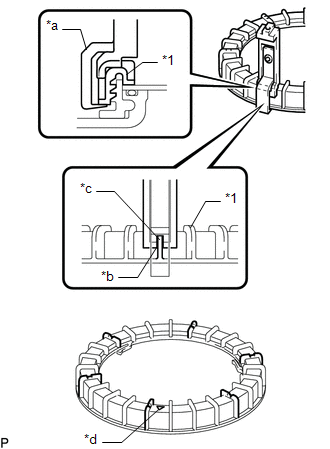
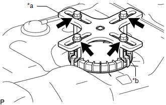
| (c) Set 4 SSTs (claw sets) to the fuel pump gauge retainer and temporarily install.
SST: 09808-14031 09808-01080 09808-01090 09808-01100
NOTICE:
- Align the cutout of SST (claw set) to the rib of the fuel pump gauge retainer.
- Do not place SST on the rotational start point mark of the fuel pump
gauge retainer, otherwise SST (claw set) cannot be set correctly.
|
 |
|
*1 | Fuel Pump Gauge Retainer | |
*a | SST (claw set) | |
*b | Rib | |
*c | Cutout | |
*d | SST (Claw Set) Incorrect Installation Point (Rotational Start Point Mark of Fuel Pump Gauge Retainer) | | |
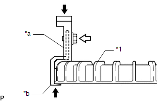
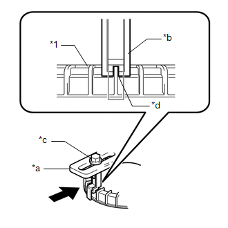
(d) While firmly pressing the claw of SST into rib of the fuel pump gauge retainer, tighten the bolt.
|
*1 | Fuel Pump Gauge Retainer | |
*a | SST (Claw Set) | |
*b | Hook |
 |
Press |
 |
SST (Bolt) | (e) Temporarily install SST (plate) to SST (claw set) with 4 SSTs (bolts).
|
*a | SST (Plate) | |
*b | SST (Claw Set) | |
|
SST (Bolt) |
| (f)
Adjust the position of SST (plate) so that the setting hole of SST
(handle) aligns with the center of the fuel pump gauge retainer. |
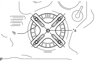 |
|
*a | Center of Fuel Pump Gauge Retainer | |
*b | SST (Plate) | | |
(g) While firmly pressing the SST (claw set) into rib of the fuel pump gauge retainer, tighten SST (bolt).
|
*1 | Fuel Pump Gauge Retainer | |
*a | SST (Plate) | |
*b | SST (Claw Set) | |
*c | SST (Bolt) | |
*d | Rib | |
|
Press | (h) Install SST (handle) to SST (plate).
SST: 09808-14031 09808-01010 09808-01020 (i) Slowly loosen the fuel pump gauge retainer by approximately 90°.
NOTICE:
- Do not use any tools other than SST, such as a screwdriver, etc.
- Do not use excessive force when pressing down on SST, as the fuel tank
vent tube assembly will place excessive force on the pump gauge retainer
and be difficult to remove, and parts may be damaged.
- Do not use an impact wrench or turn the SST handle with excessive force, as parts may be damaged.
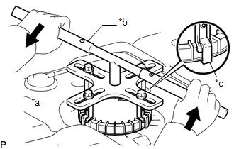
|
*a | SST (Plate) | |
*b | SST (Handle) | |
*c | SST (Claw Set) | |
|
Loosen | (j)
While one person slowly loosens the fuel pump gauge retainer, have
another person press down the rising fuel suction with pump and gauge
tube assembly, securely attach the protrusion of the fuel suction with
pump and gauge tube assembly to the groove of the fuel tank assembly,
and then remove the fuel pump gauge retainer while making sure that the
fuel suction with pump and gauge tube assembly is properly aligned.
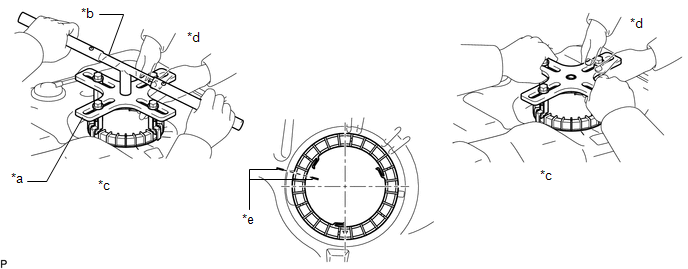
|
*a | SST (Plate) |
*b | SST (Handle) | |
*c | Person in Charge of Loosening |
*d | Person in Charge of Supporting | |
*e | Co-rotation Prevention Check Mark |
- | - |
NOTICE:
- The fuel suction with pump and gauge tube assembly is equipped with a
spring that pushes against the bottom of the fuel tank assembly to
constantly lift the fuel suction with pump and gauge tube assembly
upwards.
- If the fuel suction with pump and gauge tube assembly and fuel tank
assembly are not firmly attached and the fuel pump gauge retainer is
rotated, the fuel suction with pump and gauge tube assembly will
co-rotate and result in the fuel suction with pump and gauge tube
assembly and fuel tank assembly being damaged.
- Do not rotate the fuel pump gauge retainer when the co-rotation prevention check mark is out of place.
- Do not bend the arm of the fuel sender gauge assembly.
(k) Remove the gasket from the fuel tank assembly. |


