Components COMPONENTS ILLUSTRATION 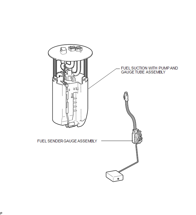 Inspection INSPECTION PROCEDURE 1. INSPECT FUEL SENDER GAUGE ASSEMBLY 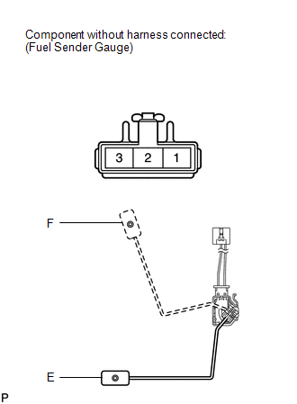 (a) Check that the float moves smoothly between F and E. (b) Measure the resistance according to the value(s) in the table below. Standard Resistance:
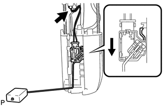
If the result is not as specified, replace the fuel sender gauge assembly. Installation INSTALLATION PROCEDURE 1. INSTALL FUEL SENDER GAUGE ASSEMBLY
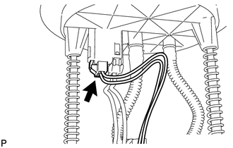
(b) Connect the fuel sender gauge connector. 2. INSTALL FUEL SUCTION WITH PUMP AND GAUGE TUBE ASSEMBLY (a) Install the fuel suction with pump and gauge tube (See page
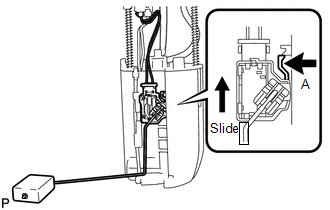
Removal REMOVAL PROCEDURE 1. REMOVE FUEL SUCTION WITH PUMP AND GAUGE TUBE ASSEMBLY (a) Remove the fuel suction with pump and gauge tube (See page
2. REMOVE FUEL SENDER GAUGE ASSEMBLY
|
Toyota Tundra Service Manual > Differential Carrier Assembly(for 3ur-fe, 3ur-fbe): Disassembly
DISASSEMBLY PROCEDURE 1. INSPECT RUNOUT OF REAR DRIVE PINION COMPANION FLANGE SUB-ASSEMBLY (a) Using a dial indicator, measure the runout of the companion flange vertically and laterally. Text in Illustration *a 72 mm (2.83 in.) Maximum runout: Runout Standard Condition Vertical runout 0.10 mm (0.00 ...