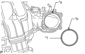
INSTALLATION PROCEDURE 1. INSTALL THROTTLE BODY ASSEMBLY
(b) Install the throttle body assembly with the 4 bolts. Torque: 10 N·m {102 kgf·cm, 7 ft·lbf} 2. INSTALL MANIFOLD ABSOLUTE PRESSURE SENSOR 3. INSTALL UNION TO CONNECTOR TUBE HOSE ASSEMBLY (a) Install the 2 wire harness brackets with the 2 bolts. Torque: 8.0 N·m {82 kgf·cm, 71 in·lbf} (b) Install the union to connector tube hose assembly with the 2 bolts. Torque: 8.2 N·m {84 kgf·cm, 73 in·lbf} (c) Connect the union to connector tube hose to the intake manifold, and slide the clamp to secure the hose. 4. INSTALL PURGE VSV (a) Install the purge VSV with the bolt. Torque: 21 N·m {214 kgf·cm, 15 ft·lbf} (b) Connect the purge line hose to the intake manifold, and slide the clamp to secure the hose. 5. INSTALL VACUUM SWITCHING VALVE ASSEMBLY (for ACIS) (a) Install the vacuum switching valve assembly with the bolt. Torque: 9.0 N·m {92 kgf·cm, 80 in·lbf} (b) Connect the 2 vacuum hoses to the vacuum switching valve assembly. 6. INSTALL STUD BOLT (a) Using an E5 "TORX" socket wrench, install the 2 stud bolts. Torque: 5.0 N·m {51 kgf·cm, 44 in·lbf} 7. INSTALL V-BANK COVER BOLT (a) Install the V-bank cover bolt to the intake manifold. Torque: 10 N·m {102 kgf·cm, 7 ft·lbf} 8. INSTALL V-BANK COVER BRACKET (a) Install the V-bank cover bracket with the 2 bolts. Torque: 10 N·m {102 kgf·cm, 7 ft·lbf} 9. INSTALL FUEL TUBE SUB-ASSEMBLY (a) Install the fuel tube sub-assembly to the intake manifold with the bolt. Torque: 10 N·m {102 kgf·cm, 7 ft·lbf} 10. INSTALL INTAKE MANIFOLD
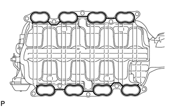
(b) Place the intake manifold on the cylinder head sub-assembly. (c) Install and uniformly tighten the 8 bolts and 2 nuts in several steps. Torque: 21 N·m {214 kgf·cm, 15 ft·lbf} (d) Connect the fuel tube sub-assembly to the fuel delivery pipe sub-assembly LH (See page
(e) Connect the fuel tube sub-assembly to the fuel delivery pipe sub-assembly RH (See page
(f) Attach the 4 clamps to the fuel tube sub-assembly. (g) Attach the 3 engine wire harness clamps to the 3 wire harness brackets. (h) Install the bolt. Torque: 8.0 N·m {82 kgf·cm, 71 in·lbf} (i) Connect the vacuum hose to the union to connector tube hose assembly, and slide the clamp to secure the hose. (j) Connect the purge line hose to the purge VSV, and slide the clamp to secure the hose. (k) Connect the 2 vacuum switching valve connectors. (l) Connect the ventilation hose to the intake manifold, and slide the clamp to secure the hose. (m) Connect the No. 4 water by-pass hose to the front water by-pass joint, and slide the clamp to secure the hose. (n) Connect the throttle body connector to the throttle body assembly. 11. INSTALL VENTILATION HOSE ASSEMBLY (a) Install the ventilation hose assembly with the bolt. Torque: 10 N·m {102 kgf·cm, 7 ft·lbf} (b) Connect the ventilation hose assembly to the ventilation pipe of the cylinder head cover sub-assembly LH and cylinder head cover sub-assembly RH, and slide the 2 clamps to secure the hose. 12. INSTALL AIR TUBE SUB-ASSEMBLY LH 13. INSTALL COWL TOP OUTER PANEL SUB-ASSEMBLY (a) Install the cowl top outer panel sub-assembly with the 7 bolts. Torque: 7.5 N·m {76 kgf·cm, 66 in·lbf} (b) Connect the washer hose and attach the 2 wire harness clamps. 14. INSTALL FRONT WIPER MOTOR AND LINK ASSEMBLY (See page
15. INSTALL EGR VALVE ASSEMBLY (See page
16. INSPECT FOR FUEL LEAK
|
Toyota Tundra Service Manual > Lane Departure Alert System: Freeze Frame Data
FREEZE FRAME DATA DESCRIPTION (a) Whenever a lane departure alert system is stored, the forward recognition camera stores the current vehicle state (ECU and sensor information) as Freeze Frame Data. CHECK FREEZE FRAME DATA (a) Connect the Techstream to the DLC3. (b) Turn the ignition switch to ON. ( ...