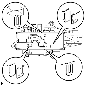
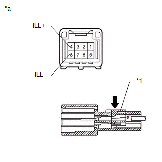
REASSEMBLY PROCEDURE 1. INSTALL SHIFT LOCK CONTROL ECU (a) Attach the 3 claws to install the shift lock control ECU to the shift lever assembly. (b) Connect the shift lock solenoid connector. 2. INSTALL POSITION INDICATOR LED (a) Attach the claw to install the position indicator LED to the lower position indicator housing. 3. INSTALL INDICATOR LIGHT WIRE SUB-ASSEMBLY (a) Connect the connector and install the indicator light wire sub-assembly to the lower position indicator housing. 4. INSTALL LOWER POSITION INDICATOR HOUSING
5. CONNECT INDICATOR LIGHT WIRE SUB-ASSEMBLY (a) Attach the 4 guides.
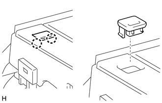
6. INSTALL NO. 2 POSITION INDICATOR SLIDE COVER (a) Install the No. 2 position indicator slide cover to the position indicator slide cover. 7. INSTALL POSITION INDICATOR SLIDE COVER (a) Install the position indicator slide cover with the No. 2 position indicator slide cover to the shift lever assembly. HINT: Install the position indicator slide cover so that its mark faces the vehicle front. 8. INSTALL UPPER POSITION INDICATOR HOUSING (a) Attach the 4 claws to install the upper position indicator housing to the shift lever assembly. 9. INSTALL SHIFT LEVER CAP
|
Toyota Tundra Service Manual > Cruise Control System: Dtc Check / Clear
DTC CHECK / CLEAR CHECK DTC (a) Connect the Techstream to the DLC3. (b) Turn the ignition switch ON. (c) Turn the Techstream on. (d) Enter the following menus: Powertrain / Cruise Control / Trouble Codes. (e) Check for DTCs. CLEAR DTC (a) Connect the Techstream to the DLC3. (b) Turn the ignition swi ...