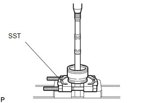
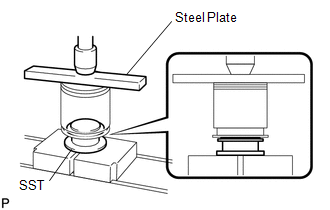
REASSEMBLY CAUTION / NOTICE / HINT
NOTICE: Do
not allow brake fluid, front differential oil, gasoline, or battery
fluid to contact the drive shaft boots, as they may damage the boots. PROCEDURE
1. INSTALL DUST SEAL | (a) Using SST and a press, press in a new dust seal to the outboard joint shaft.
SST: 09950-00020 NOTICE: Be careful not to damage the dust seal. |
|
2. INSTALL FRONT DRIVE SHAFT DUST COVER LH
| (a) Using SST, a steel plate and press, press in a new dust cover.
SST: 09316-20011 NOTICE: Be careful not to damage the dust cover. |
|
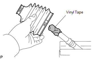
3. INSTALL OUTBOARD JOINT BOOT
| (a) Place 2 new boot clamps on the boot. HINT: Before installing the boot, wrap vinyl tape around the spline of the shaft to prevent damaging the boot. |
|
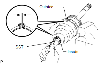
(b) Temporarily install a new boot to the outboard joint shaft. (c) Position the inside clamp onto the boot.
| (d) Using SST, pinch the inside clamp. SST: 09521-24010
NOTICE: Do not overtighten SST. | |
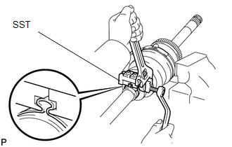
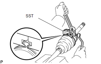
(e) Pack the outboard joint and boot with grease in the boot kit. Standard grease capacity:
292 to 312 g (10.3 to 11.0 oz.) (f) Position the outside clamp onto the boot.
| (g) Using SST, pinch the outside clamp. SST: 09521-24010
NOTICE: Do not overtighten SST. | |
| (h) Using SST, adjust the clearance of the clamps. SST: 09240-00020
Standard clearance: |
Clamp | Specified Condition | |
Inside | 2.8 to 3.8 mm (0.110 to 0.150 in.) | |
Outside | 3.5 to 4.5 mm (0.138 to 0.177 in.) | |
|
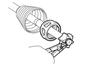
4. TEMPORARILY INSTALL INBOARD JOINT BOOT (a) Temporarily install 2 new boot clamps and a boot to the outboard joint shaft.
5. INSTALL INBOARD JOINT SHAFT
| (a) Install the cage to the outboard joint shaft. NOTICE:
Insert the cage with its smaller inner diameter side facing the outboard joint. |
|
| (b) Align the matchmarks placed before removal. | |
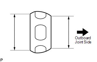
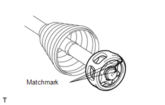
(c) Install the inner race.
| (d) Using a snap ring expander, install a new snap ring. |
|
| (e) Align the matchmarks placed before removal, and install the cage to the inner race. |
|
| (f) Install the 6 balls. HINT: Apply grease onto the balls to keep them from falling out. |
|
(g) Pack the inboard joint shaft and boot with grease in the boot kit.
Standard grease capacity: 380 to 400 g (13.3 to 14.1 oz.)
| (h) Align the matchmarks placed before removal, and install the inboard joint shaft to the outboard joint shaft. |
|
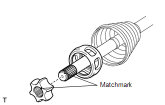
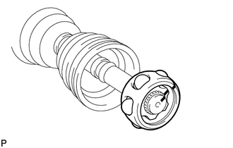
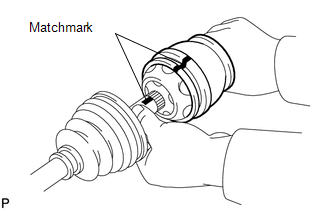
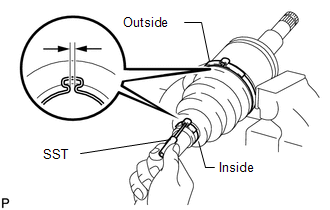
(i) Install a new snap ring. (j) Temporarily install the boot to the inboard joint shaft.
HINT: Make sure that the boot is on the shaft groove.
| (k) Check that the 2 boots are not stretched or contracted when the drive shaft is at standard length.
Standard drive shaft length (A): 625.8 mm (2.05 ft.) If the boots are stretched or contracted, correct them. |
|
| (l) Install the inboard joint boot clamps in the same manner as the outboard side.
HINT: Adjust the clearance of the inboard joint boot clamps.
Standard clearance: |
Clamp | Specified Condition | |
Inside | 2.8 to 3.8 mm (0.110 to 0.150 in.) | |
Outside | 3.0 to 4.0 mm (0.118 to 0.158 in.) | |
|
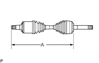
6. INSPECT FRONT DRIVE SHAFT ASSEMBLY |