REMOVAL CAUTION / NOTICE / HINT HINT:
PROCEDURE 1. REMOVE FRONT WHEEL 2. REMOVE NO. 1 ENGINE UNDER COVER 3. DRAIN DIFFERENTIAL OIL 4. DISCONNECT FRONT SPEED SENSOR LH (a) Disconnect the front speed sensor LH (see page
5. REMOVE FRONT AXLE HUB GREASE CAP 6. REMOVE AXLE HUB NUT
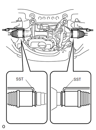
7. REMOVE TIE ROD END SUB-ASSEMBLY 8. DISCONNECT FRONT LOWER BALL JOINT ATTACHMENT LH 9. DISCONNECT FRONT DRIVE SHAFT ASSEMBLY LH (a) Using plastic-faced hammer, disconnect the drive shaft from the axle hub side. (b) Push the steering knuckle outward and disconnect the drive shaft from the steering knuckle. 10. REMOVE FRONT DRIVE SHAFT ASSEMBLY LH
(b) Using a screwdriver, remove the snap ring from the inboard joint shaft. |
Toyota Tundra Service Manual > Blind Spot Monitor System: Software Incompatibility with Body Control Module "B" (U1331)
DESCRIPTION This DTC is stored when the destination information of the main body ECU (multiplex network body ECU) does not match that of the blind spot monitor sensors. DTC Code DTC Detection Condition Trouble Area U1331 Destination information of the main body ECU (multiplex network body ECU) and b ...