DESCRIPTION
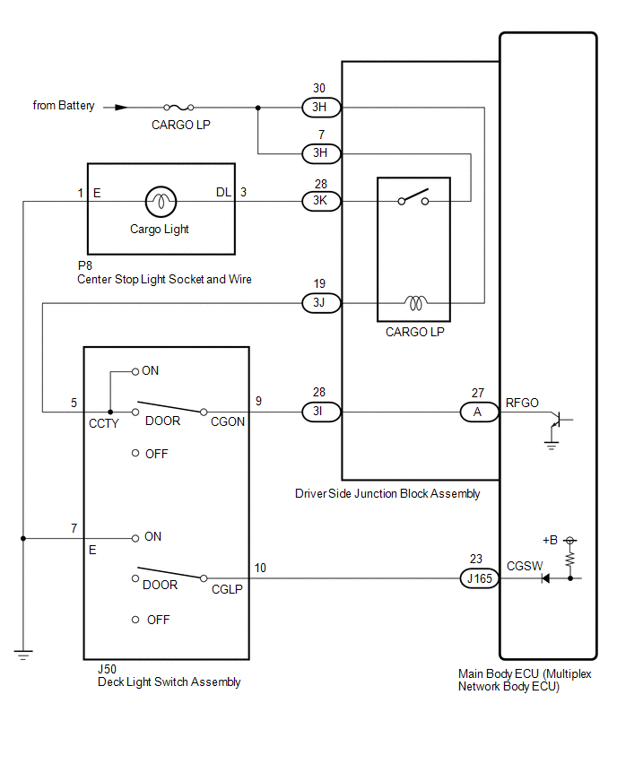
The main body ECU (multiplex network body ECU) receives a cargo light information
signal from the deck light switch assembly and door courtesy light switch, and illuminates
the cargo light.
WIRING DIAGRAM
CAUTION / NOTICE / HINT
NOTICE:
Inspect the fuses and bulbs for circuits related to this system before performing
the following procedure.
PROCEDURE
|
1.
|
PERFORM ACTIVE TEST USING TECHSTREAM
|
(a) Using the Techstream, perform the Active Test.
Click here 
Main Body
|
Tester Display
|
Test Part
|
Control Range
|
Diagnostic Note
|
|
Cargo Light
|
Cargo light
|
OFF or ON
|
Deck light switch assembly is DOOR or on position.
|
OK:
Cargo light turns on / turns off.
| OK |
 |
PROCEED TO NEXT SUSPECTED AREA SHOWN IN PROBLEM SYMPTOMS TABLE
|
| NG |

|
|
|
2.
|
READ VALUE USING TECHSTREAM
|
(a) Using the Techstream, read the Data List.
Click here
Main Body
|
Tester Display
|
Measurement Item / Range
|
Normal Condition
|
Diagnostic Note
|
|
Deck light switch assembly
|
Deck light switch assembly signal / OFF or ON
|
OFF: Deck light switch assembly off
ON: Deck light switch assembly on
|
-
|
OK:
Normal condition listed above are displayed.
| NG |
|
GO TO STEP 9
|
| OK |
|
|
|
|
3.
|
CHECK HARNESS AND CONNECTOR (CENTER STOP LIGHT SOCKET AND WIRE - BATTERY)
|
|
(a) Disconnect the center stop light socket and wire connector.
|
|
|
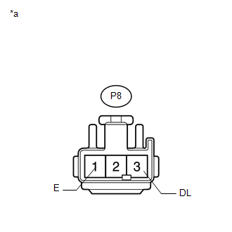
*a
|
Front view of wire harness connector
(to Center Stop Light Socket and Wire)
|
|
|
(b) Measure the voltage according to the value(s) in the table below.
Standard Voltage:
|
Tester Connection
|
Switch Condition
|
Specified Condition
|
|
P8-3 (DL) - Body ground
|
Deck light switch assembly on
|
11 to 14 V
|
|
Deck light switch assembly DOOR, door is open
|
11 to 14 V
|
|
Deck light switch assembly off
|
Below 1 V
|
| OK |
|
REPLACE MAIN BODY ECU (MULTIPLEX NETWORK BODY ECU)
|
| NG |
|
|
|
|
4.
|
CHECK HARNESS AND CONNECTOR (CENTER STOP LIGHT SOCKET AND WIRE - BODY
GROUND)
|
|
(a) Disconnect the center stop light socket and wire connector.
|
|
|
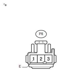
*a
|
Front view of wire harness connector
(to Center Stop Light Socket and Wire)
|
|
|
(b) Measure the resistance according to the value(s) in the table below.
Standard Resistance:
|
Tester Connection
|
Condition
|
Specified Condition
|
|
P8-1 (E) - Body ground
|
Always
|
Below 1 Ω
|
| NG |
|
REPAIR OR REPLACE HARNESS OR CONNECTOR
|
| OK |
|
|
|
|
5.
|
INSPECT DECK LIGHT SWITCH ASSEMBLY
|
(a) Remove the deck light switch assembly.
Click here
(b) Inspect the deck light switch assembly.
Click here
| NG |
|
REPLACE DECK LIGHT SWITCH ASSEMBLY
|
| OK |
|
|
|
|
6.
|
CHECK HARNESS AND CONNECTOR (DRIVER SIDE JUNCTION BLOCK ASSEMBLY - BATTERY)
|
|
(a) Disconnect the driver side junction block assembly connector.
|
|
|
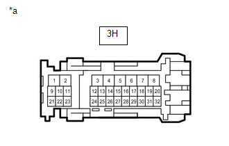
*a
|
Front view of wire harness connector
(to Driver Side Junction Block Assembly)
|
|
|
(b) Measure the voltage according to the value(s) in the table below.
Standard Voltage:
|
Tester Connection
|
Condition
|
Specified Condition
|
|
3H-7 - Body ground
|
Always
|
11 to 14 V
|
|
3H-30 - Body ground
|
Always
|
11 to 14 V
|
| NG |
|
REPAIR OR REPLACE HARNESS OR CONNECTOR
|
| OK |
|
|
|
|
7.
|
CHECK HARNESS AND CONNECTOR (DRIVER SIDE JUNCTION BLOCK ASSEMBLY - CENTER
STOP LIGHT SOCKET AND WIRE AND DECK LIGHT SWITCH ASSEMBLY)
|
(a) Disconnect the 3J and 3K driver side junction block assembly connectors.
(b) Disconnect the P8 center stop light socket and wire connector.
(c) Disconnect the J50 deck light switch assembly connector.
(d) Measure the resistance according to the value(s) in the table below.
Standard Resistance:
|
Tester Connection
|
Condition
|
Specified Condition
|
|
3K-28 - P8-3 (DL)
|
Always
|
Below 1 Ω
|
|
3J-19 - J50-5 (CCTY)
|
Always
|
Below 1 Ω
|
|
3I-28 - J50-9 (CGON)
|
Always
|
Below 1 Ω
|
|
3K-28 or P8-3 (DL) - Body ground
|
Always
|
10 kΩ or higher
|
|
3J-19 or J50-5 (CCTY) - Body ground
|
Always
|
10 kΩ or higher
|
|
3I-28 or J50-9 (CGON) - Body ground
|
Always
|
10 kΩ or higher
|
| NG |
|
REPAIR OR REPLACE HARNESS OR CONNECTOR
|
| OK |
|
|
|
|
8.
|
CHECK DRIVER SIDE JUNCTION BLOCK ASSEMBLY
|
(a) Remove the driver side junction block assembly.
Click here
|
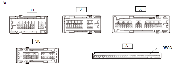
*a
|
Component without harness connected
(Driver Side Junction Block Assembly)
|
-
|
-
|
(b) Remove the main body ECU (multiplex network body ECU) from the driver side
junction block assembly.
Click here
(c) Measure the resistance according to the value(s) in the table below.
Standard Resistance:
|
Tester Connection
|
Condition
|
Specified Condition
|
|
3K-28 - 3H-7
|
Battery positive (+) → 3H-30
Battery negative (-) → 3J-19
|
Below 1 Ω
|
|
Battery not connected to 3J-19 and 3H-30
|
10 kΩ or higher
|
|
3I-28 - A-27 (RFGO)
|
Always
|
Below 1 Ω
|
| OK |
|
REPLACE MAIN BODY ECU (MULTIPLEX NETWORK BODY ECU)
|
| NG |
|
REPLACE DRIVER SIDE JUNCTION BLOCK ASSEMBLY
|
|
9.
|
INSPECT DECK LIGHT SWITCH ASSEMBLY
|
(a) Remove the deck light switch assembly.
Click here
(b) Inspect the deck light switch assembly.
Click here
| NG |
|
REPLACE DECK LIGHT SWITCH ASSEMBLY
|
| OK |
|
|
|
|
10.
|
CHECK HARNESS AND CONNECTOR (DECK LIGHT SWITCH ASSEMBLY - MAIN BODY ECU
[MULTIPLEX NETWORK BODY ECU] AND BODY GROUND)
|
(a) Disconnect the J50 deck light switch assembly connector.
(b) Disconnect the J165 main body ECU (multiplex network body ECU) connector.
(c) Measure the resistance according to the value(s) in the table below.
Standard Resistance:
|
Tester Connection
|
Condition
|
Specified Condition
|
|
J50-10 (CGLP) - J165-23 (CGSW)
|
Always
|
Below 1 Ω
|
|
J50-7 (E) - Body ground
|
Always
|
Below 1 Ω
|
|
J50-10 (CGLP) or J165-23 (CGSW) - Body ground
|
Always
|
10 kΩ or higher
|
| OK |
|
REPLACE MAIN BODY ECU (MULTIPLEX NETWORK BODY ECU)
|
| NG |
|
REPAIR OR REPLACE HARNESS OR CONNECTOR
|
| 

