REMOVAL PROCEDURE 1. REMOVE FRONT PILLAR GARNISH LH 2. REMOVE FRONT PILLAR GARNISH RH 3. REMOVE NO. 1 INSTRUMENT PANEL SPEAKER PANEL SUB-ASSEMBLY 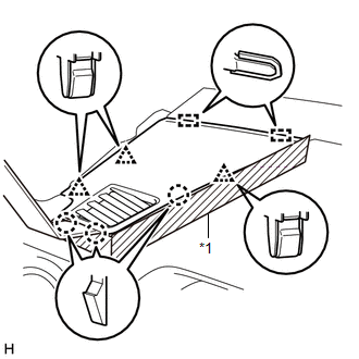 Text in Illustration Text in Illustration
(a) Apply protective tape as shown in the illustration. (b) Using moulding remover B, detach the 3 clips, 3 claws and 2 guides and remove the No. 1 instrument panel speaker panel sub-assembly. 4. REMOVE NO. 2 INSTRUMENT PANEL SPEAKER PANEL SUB-ASSEMBLY 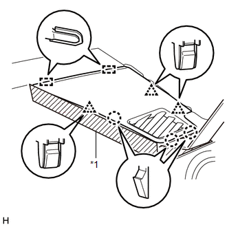 Text in Illustration Text in Illustration
(a) Apply protective tape as shown in the illustration. (b) Using moulding remover B, detach the 3 clips, 3 claws and 2 guides and remove the No. 2 instrument panel speaker panel sub-assembly. 5. REMOVE FRONT NO. 2 SPEAKER ASSEMBLY LH (a) Remove the 2 bolts. 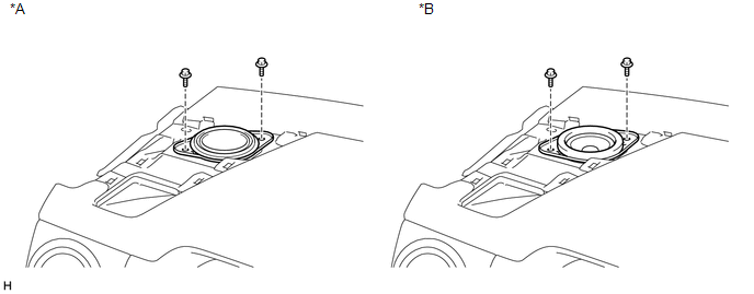 Text in Illustration Text in Illustration
(b) Disconnect the connector and remove the front No. 2 speaker assembly LH. NOTICE: Do not touch the cone part of the speaker. 6. REMOVE FRONT NO. 2 SPEAKER ASSEMBLY RH 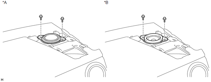 Text in Illustration Text in Illustration
(a) Remove the 2 bolts. (b) Disconnect the connector and remove the front No. 2 speaker assembly RH. NOTICE: Do not touch the cone part of the speaker. 7. REMOVE NO. 1 SPEAKER HOLE COVER 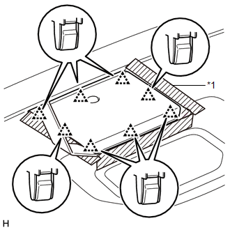 Text in Illustration Text in Illustration
(a) Apply protective tape as shown in the illustration. (b) Using moulding remover B, detach the 8 clips and remove the No. 1 speaker hole cover. 8. REMOVE FRONT NO. 4 SPEAKER ASSEMBLY (for 7 Speakers) 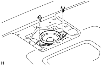 (a) Remove the 2 bolts. (b) Disconnect the connector and remove the front No. 4 speaker assembly. NOTICE: Do not touch the cone part of the speaker. |
Toyota Tundra Service Manual > Power Tilt And Power Telescopic Steering Column System: Tilt and Telescopic Manual Switch Circuit
DESCRIPTION Different voltage values are sent to the multiplex tilt and telescopic ECU by operating the tilt and telescopic switch (headlight dimmer switch assembly). The multiplex tilt and telescopic ECU then judges which motor and in which direction that motor should operate based on the voltage v ...


