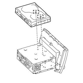
INSTALLATION PROCEDURE 1. INSTALL STEREO COMPONENT TUNER ASSEMBLY
2. INSTALL NO. 2 RADIO RECEIVER BRACKET (a) Install the No. 2 radio receiver bracket with the 5 bolts. Torque: 3.5 N·m {36 kgf·cm, 31 in·lbf} 3. INSTALL NO. 1 RADIO RECEIVER BRACKET (a) Install the No. 1 radio receiver bracket with the 5 bolts. Torque: 3.5 N·m {36 kgf·cm, 31 in·lbf} 4. INSTALL NO. 1 NAVIGATION WIRE (a) Connect each connector to install the No. 1 navigation wire. 5. INSTALL RADIO AND DISPLAY RECEIVER ASSEMBLY 6. INSTALL AIR CONDITIONING CONTROL ASSEMBLY 7. INSTALL UPPER CONSOLE PANEL SUB-ASSEMBLY 8. INSTALL REAR UPPER CONSOLE PANEL SUB-ASSEMBLY 9. INSTALL SHIFT LEVER KNOB SUB-ASSEMBLY 10. CONNECT CABLE TO NEGATIVE BATTERY TERMINAL NOTICE: When disconnecting the cable, some systems need to be initialized after the cable is reconnected (See page
|
Toyota Tundra Service Manual > Automatic Transmission System: Transmission Fluid Temperature Sensor "A" Circuit Low Input (P0712,P0713)
DESCRIPTION Refer to DTC P0711 (See page ). DTC Code DTC Detection Condition Trouble Area P0712 ATF temperature sensor resistance is below 79 Ω for 0.5 sec. or more (1-trip detection logic). Short in ATF temperature sensor circuit ATF temperature sensor ECM P0713 ATF temperature sensor resistance i ...