DESCRIPTION This DTC is
stored if the navigation receiver assembly judges as a result of its
self check that the signals or signal lines between the navigation
receiver assembly and the television camera assembly are not normal. |
DTC Code | DTC Detection Condition |
Trouble Area | | C1622 |
Open or Short Circuit in television camera signal |
- Harness or connector
- Television camera assembly
- Navigation receiver assembly
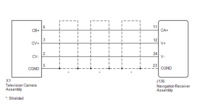
| WIRING DIAGRAM
 PROCEDURE
(a) Clear the DTCs (See page
 ). ). (b) Check for DTCs (See page
). Result |
Result | Proceed to | |
No DTC is output | A | |
DTC is output | B |
| A |
 | USE SIMULATION METHOD TO CHECK |
|
B |
 | |
| 2. |
CHECK HARNESS AND CONNECTOR (NAVIGATION RECEIVER ASSEMBLY - TELEVISION CAMERA ASSEMBLY) |
(a) Disconnect the J136 navigation receiver assembly connector. (b) Disconnect the X1 television camera assembly connector.
(c) Measure the resistance according to the value(s) in the table below.
Standard Resistance: |
Tester Connection | Condition |
Specified Condition | |
J136-11 (CA+) - X1-6 (CB+) |
Always | Below 1 Ω | |
J136-12 (V+) - X1-3 (CV+) |
Always | Below 1 Ω | |
J136-23 (CGND) - X1-5 (CGND) |
Always | Below 1 Ω | |
J136-24 (V-) - X1-2 (CV-) |
Always | Below 1 Ω | |
J136-11 (CA+) - Body ground |
Always | 10 kΩ or higher | |
J136-12 (V+) - Body ground |
Always | 10 kΩ or higher | |
J136-23 (CGND) - Body ground |
Always | 10 kΩ or higher | |
J136-24 (V-) - Body ground |
Always | 10 kΩ or higher |
| NG |
| REPAIR OR REPLACE HARNESS OR CONNECTOR |
|
OK | |
| |
| 3. |
CHECK NAVIGATION RECEIVER ASSEMBLY |
| (a) Measure the resistance according to the value(s) in the table below.
Standard Resistance: |
Tester Connection | Condition |
Specified Condition | |
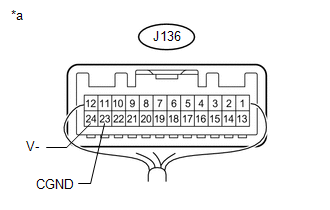
J136-23 (CGND) - Body ground |
Always | Below 1 Ω | |
J136-24 (V-) - Body ground |
Always | Below 1 Ω | Text in Illustration |
*a | Component with harness connected
(Navigation Receiver Assembly) | Result |
Result | Proceed to | |
OK | A | |
NG (for Column Shift Type) |
B | | NG (for Floor Shift Type) |
C | | |
| B |
| REPLACE NAVIGATION RECEIVER ASSEMBLY |
| C |
| REPLACE NAVIGATION RECEIVER ASSEMBLY |
|
A | |
| |
| 4. |
CHECK NAVIGATION RECEIVER ASSEMBLY |
| (a) Disconnect the television camera assembly connector. |
|
(b) Measure the voltage according to the value(s) in the table below. Standard Voltage: |
Tester Connection | Switch Condition |
Specified Condition | |
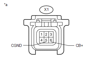
X1-6 (CB+) - X1-5 (CGND) |
Ignition switch ACC | 5.5 to 7.05 V | Text in Illustration |
*a | Front view of wire harness connector
(to Television Camera Assembly) | Result |
Result | Proceed to | |
OK | A | |
NG (for Column Shift Type) |
B | | NG (for Floor Shift Type) |
C |
| B |
| REPLACE NAVIGATION RECEIVER ASSEMBLY |
| C |
| REPLACE NAVIGATION RECEIVER ASSEMBLY |
|
A | |
| |
| 5. |
CHECK TELEVISION CAMERA ASSEMBLY | (a) Using an oscilloscope, check the waveform.
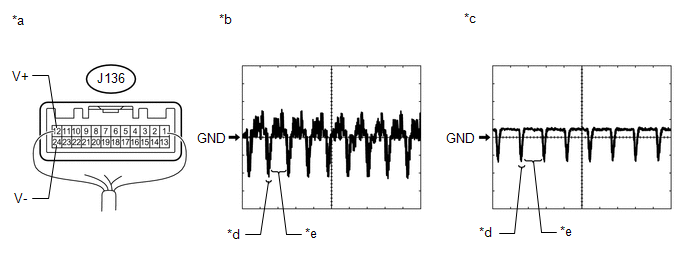 Text in Illustration Text in Illustration |
*a | Component with harness connected
(Navigation Receiver Assembly) |
*b | Waveform 1 | |
*c | Waveform 2 |
*d | Synchronized Signal | |
*e | Video Waveform |
- | - | Measurement Condition |
Item | Content | |
Tester Connection | J136-12 (V+) - J136-24 (V-) | |
Tool Setting | 0.2 V/DIV., 50 μs/DIV. | |
Condition |
- Waveform 1: Ignition switch ON
- Waveform 2: Ignition switch ON, screen blacked out by covering camera lens
| OK: Waveform is as shown in illustration.
HINT: The video waveform changes according to the image sent by the television camera assembly.
| OK |
| USE SIMULATION METHOD TO CHECK |
|
NG | |
| |
| 6. |
REPLACE TELEVISION CAMERA ASSEMBLY | (a) Replace the television camera assembly with a new or normally functioning one (See page
).
|
NEXT | |
| |
(a) Clear the DTCs (See page
). (b) Check for DTCs (See page
). Result |
Result | Proceed to | |
No DTC is output | A | |
DTC is output (for Column Shift Type) |
B | | DTC is output (for Floor Shift Type) |
C |
| A |
| END (TELEVISION CAMERA ASSEMBLY WAS DEFECTIVE) |
| B |
| REPLACE NAVIGATION RECEIVER ASSEMBLY |
| C |
| REPLACE NAVIGATION RECEIVER ASSEMBLY | |