DESCRIPTION The throttle actuator is operated by the ECM and opens and closes the throttle valve using gears.
The
opening angle of the throttle valve is detected by the Throttle
Position (TP) sensor, which is mounted on the throttle with motor body
assembly. The TP sensor provides feedback to the ECM. This feedback
allows the ECM to appropriately control the throttle actuator and
monitor the throttle opening angle as the ECM responds to driver inputs. HINT:
This ETCS (Electronic Throttle Control System) does not use a throttle cable. |
DTC No. | DTC Detection Condition |
Trouble Area | | P2102 |
Conditions (a) and (b) continue for 2.0 seconds (1 trip detection logic):
(a) Throttle actuator duty ratio 80% or more (b) Throttle actuator current less than 0.5 A |
- Open in throttle actuator circuit
- Throttle actuator
- ECM
| | P2103 |
Either of following conditions met (1 trip detection logic):
- Motor driver IC diagnosis signal failure
- Motor driver IC current limiter port failure
|
- Short in throttle actuator circuit
- Throttle actuator
- Throttle valve
- Throttle with motor body assembly
- ECM
| MONITOR DESCRIPTION
The
ECM monitors the electrical current through the electronic actuator,
and detects malfunctions and open circuits in the throttle actuator
based on this value. If the current is outside the standard range, the
ECM determines that there is a malfunction in the throttle actuator. In
addition, if the throttle valve does not function properly (for example,
stuck on), the ECM determines that there is a malfunction. The ECM then
illuminates the MIL and stores a DTC. Example: When
the electrical current is less than 0.5 A and the throttle actuator
duty ratio exceeds 80%, the ECM interprets this as the current being
outside the standard range, and illuminates the MIL and stores a DTC. If
the malfunction is not repaired successfully, a DTC is stored when the
engine is quickly revved to a high rpm several times after the engine is
started and has idled for 5 seconds. MONITOR STRATEGY |
Related DTCs | P2102: Throttle actuator current (low current)
P2103: Throttle actuator current (high current) | |
Required Sensors/Components (Main) | Throttle actuator (throttle body) | |
Required Sensors/Components (Related) |
None | | Frequency of Operation |
Continuous | | Duration |
2 seconds: P2102 25 times: P2103 (Case 1) 0.6 seconds: P2103 (Case 2) | |
MIL Operation | Immediate | |
Sequence of Operation | None | TYPICAL ENABLING CONDITIONS |
Monitor runs whenever following DTCs not present |
None | P2102 |
Throttle actuator | ON | |
Duty-cycle to throttle actuator | 80% or more | |
Throttle actuator power supply | 8 V or more | P2103 |
Battery voltage | 8 V or more | |
Starter | OFF | |
Electronic throttle actuator | ON | |
Either of the following conditions 1 or 2 met: |
- | | 1. Electronic throttle actuator power supply voltage |
8 V or more | | 2. Electronic throttle actuator power |
ON | TYPICAL MALFUNCTION THRESHOLDS P2102 |
Motor current | Less than 0.5 A | P2103 (Case 1) |
Motor driver IC high current inhibit signal |
ON | P2103 (Case 2) |
Motor driver IC high current limiter monitor input |
Fail | CONFIRMATION DRIVING PATTERN
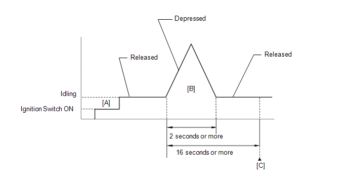
- Connect the Techstream to the DLC3.
- Turn the ignition switch to ON and turn the Techstream on.
- Clear DTCs (even if no DTCs are stored, perform the clear DTC operation).
- Turn the ignition switch off and wait for at least 30 seconds.
- Turn the ignition switch to ON and turn the Techstream on [A].
- Start the engine.
- With the vehicle stationary, fully depress the accelerator pedal and quickly release it [B].
- Check that 16 seconds or more have elapsed from the instant when the accelerator pedal is first depressed.
- Enter the following menus: Powertrain / Engine and ECT / Trouble Codes [C].
- Read the pending DTCs.
HINT:
- If a pending DTC is output, the system is malfunctioning.
- If a pending DTC is not output, perform the following procedure.
- Enter the following menus: Powertrain / Engine and ECT / Utility / All Readiness.
- Input the DTC: P2102 or P2103.
- Check the DTC judgment result.
|
Tester Display |
Description |
|
NORMAL |
- DTC judgment completed
- System normal
|
|
ABNORMAL |
- DTC judgment completed
- System abnormal
|
|
INCOMPLETE |
- DTC judgment not completed
- Perform driving pattern after confirming DTC enabling conditions
|
|
N/A |
- Unable to perform DTC judgment
- Number of DTCs which do not fulfill DTC preconditions has reached ECU memory limit
|
HINT:
- If the judgment result shows ABNORMAL, the system has a malfunction.
- If the judgment result shows INCOMPLETE or N/A, perform steps [B] through [C] again.
- If no pending DTC is output, perform a universal trip and check for permanent DTCs (See page
 ). ).
HINT:
- If a permanent DTC is output, the system is malfunctioning.
- If no permanent DTC is output, the system is normal.
FAIL-SAFE When
either of these DTCs, or other DTCs relating to ETCS (Electronic
Throttle Control System) malfunctions are stored, the ECM enters
fail-safe mode. During fail-safe mode, the ECM cuts the current to the
throttle actuator and the throttle valve is returned to a 7° throttle
angle by the return spring. The ECM then adjusts the engine output by
controlling the fuel injection (intermittent fuel-cut) and ignition
timing in accordance with the accelerator pedal opening angle to allow
the vehicle to continue at a minimal speed. If the accelerator pedal is
depressed firmly and gently, the vehicle can be driven slowly. Fail-safe mode continues until a pass condition is detected, and the ignition switch is then turned off. WIRING DIAGRAM
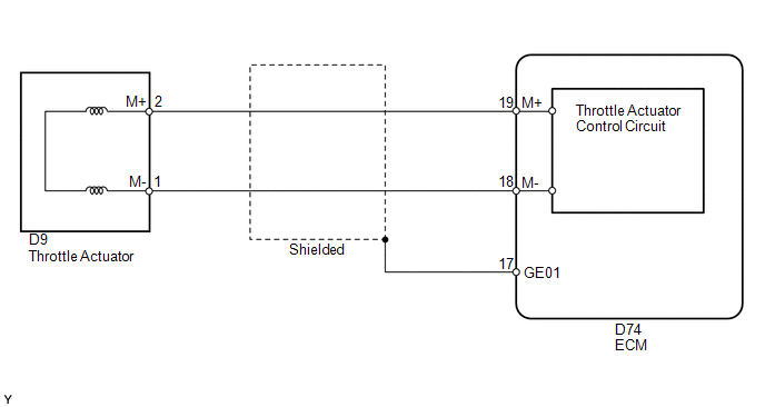 CAUTION / NOTICE / HINT
HINT:
- Read freeze frame data using the Techstream. Freeze frame data records
the engine condition when malfunctions are detected. When
troubleshooting, freeze frame data can help determine if the vehicle was
moving or stationary, if the engine was warmed up or not, if the
air-fuel ratio was lean or rich, and other data from the time the
malfunction occurred.
- The throttle actuator current (Throttle Motor Current) and the throttle
actuator duty ratio (Throttle Motor Open Duty/Throttle Motor Close Duty)
can be read using the Techstream. However, the ECM shuts off the
throttle actuator current when the ETCS malfunctions.
PROCEDURE |
1. | INSPECT THROTTLE WITH MOTOR BODY ASSEMBLY (RESISTANCE OF THROTTLE ACTUATOR) |
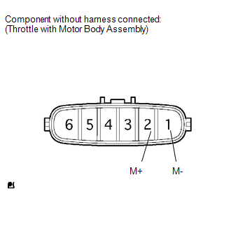 (a) Disconnect the throttle with motor body assembly connector.
(b) Measure the resistance according to the value(s) in the table below.
Standard Resistance: |
Tester Connection | Condition |
Specified Condition | |
2 (M+) - 1 (M-) | 20°C (68°F) |
0.3 to 100 Ω | HINT: Perform "Inspection After Repair" after replacing the throttle with motor body assembly (See page
).
| NG |  |
REPLACE THROTTLE WITH MOTOR BODY ASSEMBLY |
|
OK |
 | |
| 2. |
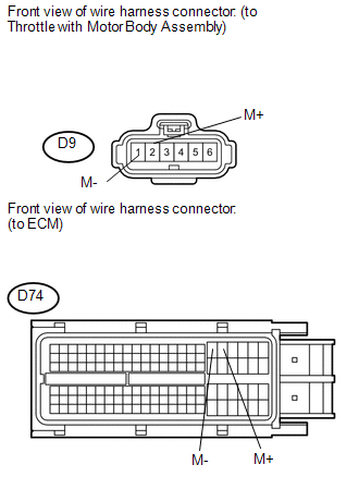
CHECK HARNESS AND CONNECTOR (THROTTLE WITH MOTOR BODY ASSEMBLY - ECM) |
 (a) Disconnect the throttle body connector.
(b) Disconnect the ECM connector. (c) Measure the resistance according to the value(s) in the table below.
Standard Resistance: |
Tester Connection | Condition |
Specified Condition | |
D9-2 (M+) - D74-19 (M+) |
Always | Below 1 Ω | |
D9-1 (M-) - D74-18 (M-) |
Always | Below 1 Ω | |
D9-2 (M+) or D74-19 (M+) - Body ground |
Always | 10 kΩ or higher | |
D9-1 (M-) or D74-18 (M-) - Body ground |
Always | 10 kΩ or higher |
| NG |
| REPAIR OR REPLACE HARNESS OR CONNECTOR |
|
OK | |
| |
| 3. |
INSPECT THROTTLE WITH MOTOR BODY ASSEMBLY |
(a) Check for foreign objects between the throttle valve and the housing.
OK: No foreign objects between throttle valve and housing. HINT:
Perform "Inspection After Repair" after cleaning the throttle with motor body assembly (See page
).
| NG | |
REMOVE FOREIGN OBJECT AND CLEAN THROTTLE WITH MOTOR BODY ASSEMBLY |
|
OK | |
| |
| 4. |
INSPECT THROTTLE VALVE | (a) Check if the throttle valve opens and closes smoothly.
OK: Throttle valve opens and closes smoothly. HINT: Perform "Inspection After Repair" after replacing the throttle with motor body assembly (See page
).
| OK | |
REPLACE ECM |
| NG |
| REPLACE THROTTLE WITH MOTOR BODY ASSEMBLY | | 

