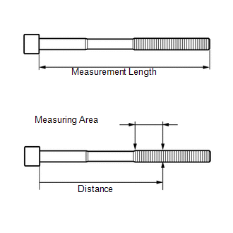
INSPECTION PROCEDURE 1. INSPECT CYLINDER HEAD SET BOLT
(b) Using a vernier caliper, measure the diameter of the elongated thread at the measuring area. Distance: 103 mm (4.06 in.) for intake side bolt. 108 mm (4.25 in.) for exhaust side bolt. Standard diameter: 10.85 to 11.00 mm (0.427 to 0.433 in.) Minimum diameter: 10.60 mm (0.417 in.) If the diameter is less than the minimum, replace the cylinder head bolt. HINT: If a visual check reveals no excessively thin areas, check the center of the bolt (refer to illustration) and find the area that has the smallest diameter. 2. INSPECT NO. 1 VALVE ROCKER ARM SUB-ASSEMBLY
3. INSPECT VALVE LASH ADJUSTER ASSEMBLY NOTICE:
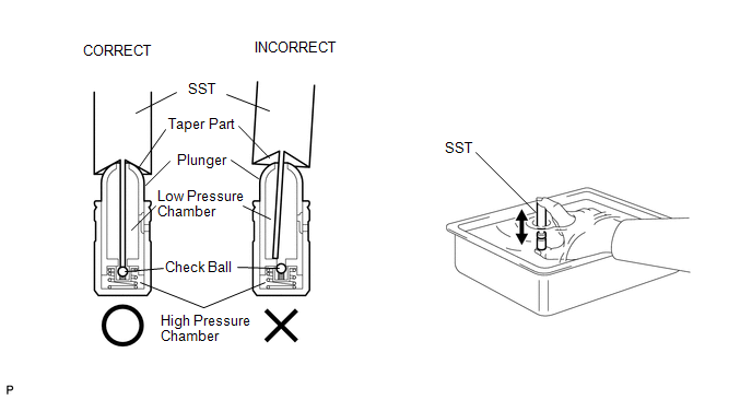 (a) Place the lash adjuster into a container full of new engine oil. (b) Insert SST's tip into the lash adjuster's plunger and use the tip to press down on the check ball inside the plunger. SST: 09276-75010 (c) Squeeze SST and the lash adjuster together to move the plunger up and down 5 to 6 times. (d) Check the movement of the plunger and bleed air. OK: Plunger moves up and down. NOTICE: When bleeding high-pressure air from the compression chamber, make sure that the tip of SST is actually pressing the check ball as shown in the illustration. If the check ball is not pressed, air will not bleed. (e) After bleeding the air, remove SST. Then try to quickly and firmly press the plunger with your fingers. OK: Plunger can be pressed 3 times. If the plunger can still be compressed after pressing it 3 times, replace the lash adjuster with a new one. 4. INSPECT CAMSHAFT SUB-ASSEMBLY 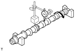 (a) Inspect the camshaft for runout. (1) Place the camshaft on V-blocks. (2) Using a dial indicator, measure the circle runout at the center journal. Maximum circle runout: 0.04 mm (0.00157 in.) If the circle runout is more than the maximum, replace the camshaft. HINT: Check the oil clearance after replacing the camshaft.
5. INSPECT CAMSHAFT TIMING GEAR (a) Install the camshaft bearing cap (See page
HINT: Only install the intake camshaft. (b) Install the camshaft housing (See page
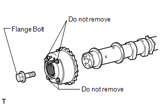
(c) Apply a light coat of engine oil on the camshaft and camshaft timing gear. 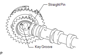 (d) Using the hexagonal portion of the camshaft, align and attach the knock pin of the camshaft with the pin hole of the camshaft timing gear. NOTICE:
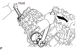
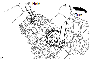
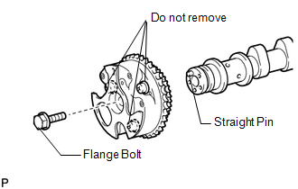
(f) Using a wrench to hold the hexagonal portion of the camshaft, install the camshaft timing gear with the bolt. Torque: 100 N·m {1020 kgf·cm, 74 ft·lbf} (g) Remove the camshaft bearing cap (See page
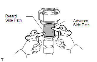
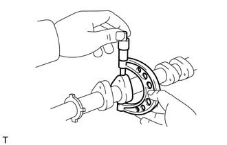
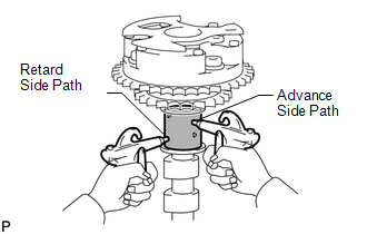
(h) Check the lock of the camshaft timing gear. (1) Clamp the camshaft in a vise, and confirm that the camshaft timing gear is locked. NOTICE: Be careful not to damage the camshaft. 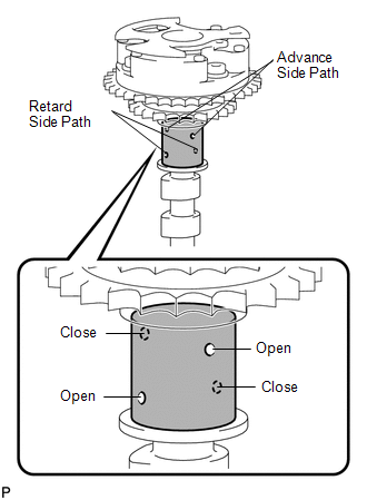 (i) Release the lock pin. (1) Cover the 4 oil paths of the cam journal with vinyl tape as shown in the illustration. (2) Break through the tape of the advance side path. Then break through the tape of the retard side path on the opposite side of the advanced side path, as shown in the illustration.
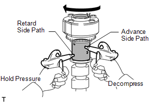
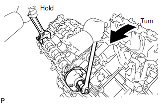
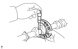
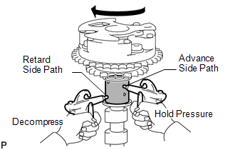
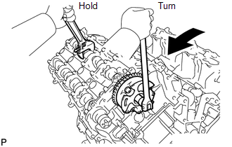
(5) When the camshaft timing gear reaches the most advanced position, release the air pressure from the retard side path and advance side path, in that order. NOTICE: Do not release the air pressure from the advance side path first. The gear may abruptly shift in the retard direction and break the lock pin. (j) Check for smooth rotation. (1) Turn the camshaft timing gear within its movable range (21°) 2 or 3 times, but do not turn it to the most retarded position. Make sure that the gear turns smoothly. NOTICE: Do not use air pressure to perform the smooth rotation check. (k) Check the lock in the most retarded position. (1) Confirm that the camshaft timing gear is locked at the most retarded position. (l) Install the camshaft bearing cap (See page
HINT: Only install the intake camshaft. (m) Install the camshaft housing (See page
(o) Remove the camshaft bearing cap (See page
6. INSPECT CAMSHAFT TIMING EXHAUST GEAR (a) Install the camshaft bearing cap (See page
HINT: Only install the exhaust camshaft. (b) Install the camshaft housing (See page
(c) Apply a light coat of engine oil on the camshaft and camshaft timing exhaust gear. 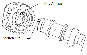 (d) Using the hexagonal portion of the camshaft, align and attach the knock pin of the camshaft with the pin hole of the camshaft timing exhaust gear. NOTICE:
(e) Apply a light coat of engine oil on the threads and under the head of the bolt.
(g) Remove the camshaft bearing cap (See page (h) Check the camshaft timing exhaust gear lock. (1) Make sure that the camshaft timing exhaust gear is locked. 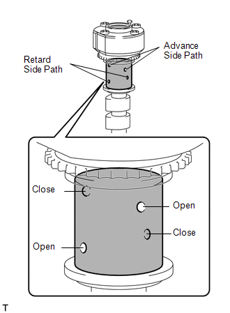 (i) Release the lock pin. (1) Cover the 4 oil paths of the cam journal with vinyl tape as shown in the illustration. (2) Break through the tape of the advance side path. Then break through the tape of the retard side path on the opposite side of the advanced side path, as shown in the illustration.
(5) When the camshaft timing exhaust gear moves to the most retarded position, release the air pressure from the advance side path, and then release the air pressure from the retard side path. NOTICE: Be sure to release the air pressure from the advance side path first. If the air pressure of the retard side path is released first, the camshaft timing exhaust gear may abruptly shift in the advance direction and break the lock pin or other parts. (j) Check for smooth rotation. (1) Turn the camshaft timing exhaust gear within its movable range (18.5°) 2 or 3 times, but do not turn it to the most advanced position. Make sure that the gear turns smoothly. NOTICE: When the air pressure is released from the advance side path and then from the retard side path, the gear automatically returns to the most advanced position due to the advance assist spring operation, and locks. Gradually release the air pressure from the retard side path before performing the smooth rotation check. (k) Check the lock at the most advanced position. (1) Make sure that the camshaft timing exhaust gear is locked at the most advanced position. (l) Install the camshaft bearing cap (See page
HINT: Only install the exhaust camshaft. (m) Install the camshaft housing (See page
(o) Remove the camshaft bearing cap (See page
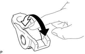
7. INSPECT NO. 1 CHAIN SUB-ASSEMBLY 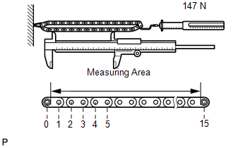 (a) Using a spring scale, pull the chain with a force of 147 N (15 kgf, 33.1 lbf) as shown in the illustration. (b) Using a vernier caliper, measure the length of 15 pins. Maximum chain elongation: 136.9 mm (5.39 in.) HINT: Perform the measurement at 3 random places. If the elongation is more than the maximum, replace the chain. 8. INSPECT NO. 2 CHAIN SUB-ASSEMBLY (a) Using a spring scale, pull the chain with a force of 147 N (15 kgf, 33.1 lbf) as shown in the illustration. (b) Using a vernier caliper, measure the length of 15 pins. Maximum chain elongation: 137.6 mm (5.42 in.) HINT: Perform the measurement at 3 random places. If the elongation is more than the maximum, replace the chain. 9. INSPECT CRANKSHAFT TIMING SPROCKET RH 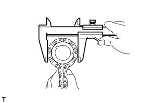 (a) Wrap the chain around the sprocket. (b) Using a vernier caliper, measure the sprocket diameter with the chain. Minimum sprocket diameter (with chain): 61.4 mm (2.42 in.) HINT: The vernier caliper must contact the chain rollers for the measurement. If the diameter is less than the minimum, replace the chain and sprocket. 10. INSPECT CRANKSHAFT TIMING SPROCKET LH (a) Wrap the chain around the sprocket. (b) Using a vernier caliper, measure the sprocket diameter with the chain. Minimum sprocket diameter (with chain): 61.4 mm (2.42 in.) HINT: The vernier caliper must contact the chain rollers for the measurement. If the diameter is less than the minimum, replace the chain and sprocket. 11. INSPECT NO. 1 CHAIN TENSIONER ASSEMBLY 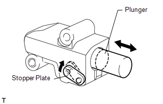 (a) Move the stopper plate upward to release the lock. Push the plunger and check that it moves smoothly. If necessary, replace the chain tensioner. 12. INSPECT NO. 2 CHAIN TENSIONER ASSEMBLY 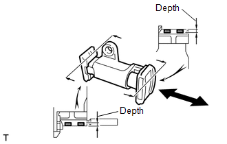 (a) Check that the plunger moves smoothly. (b) Measure the worn depth of the chain tensioner. Maximum depth: 0.9 mm (0.0354 in.) If the depth is more than the maximum, replace the chain tensioner. 13. INSPECT NO. 3 CHAIN TENSIONER ASSEMBLY 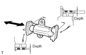 (a) Check that the plunger moves smoothly. (b) Measure the worn depth of the chain tensioner. Maximum depth: 0.9 mm (0.0354 in.) If the depth is more than the maximum, replace the chain tensioner. 14. INSPECT NO. 1 CHAIN TENSIONER SLIPPER LH 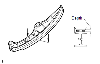 (a) Measure the worn depth of the chain tensioner slipper. Maximum depth: 1.0 mm (0.0394 in.) If the depth is more than the maximum, replace the chain tensioner slipper. 15. INSPECT NO. 1 CHAIN TENSIONER SLIPPER RH 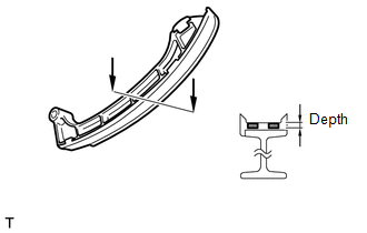 (a) Measure the worn depth of the chain tensioner slipper. Maximum depth: 1.0 mm (0.0394 in.) If the depth is more than the maximum, replace the chain tensioner slipper. 16. INSPECT NO. 1 CHAIN VIBRATION DAMPER LH 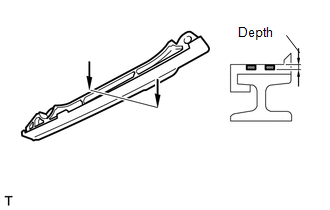 (a) Measure the worn depth of the chain vibration damper. Maximum depth: 1.0 mm (0.0394 in.) If the depth is more than the maximum, replace the chain vibration damper. 17. INSPECT NO. 1 CHAIN VIBRATION DAMPER RH 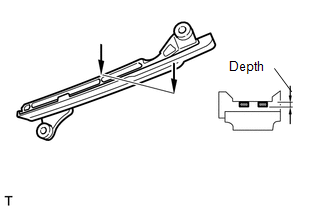 (a) Measure the worn depth of the chain vibration damper. Maximum depth: 1.0 mm (0.0394 in.) If the depth is more than the maximum, replace the chain vibration damper. 18. INSPECT EXHAUST MANIFOLD SUB-ASSEMBLY LH 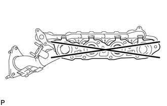 (a) Using a precision straightedge and feeler gauge, measure the warpage of the contact surface of the cylinder head. Maximum warpage: 0.7 mm (0.0276 in.) If the warpage is more than the maximum, replace the exhaust manifold. 19. INSPECT EXHAUST MANIFOLD SUB-ASSEMBLY RH 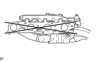 (a) Using a precision straightedge and feeler gauge, measure the warpage of the contact surface of the cylinder head. Maximum warpage: 0.7 mm (0.0276 in.) If the warpage is more than the maximum, replace the exhaust manifold. |
Toyota Tundra Service Manual > Instrument Panel Safety Pad(for Column Shift Type): Components
COMPONENTS ILLUSTRATION *1 COWL SIDE TRIM BOARD LH *2 FRONT DOOR SCUFF PLATE LH *3 INSTRUMENT CLUSTER FINISH PANEL ORNAMENT *4 INSTRUMENT SIDE PANEL LH *5 LOWER CENTER INSTRUMENT COVER *6 LOWER INSTRUMENT PANEL FINISH PANEL SUB-ASSEMBLY LH *7 LOWER NO. 1 INSTRUMENT PANEL AIRBAG ASSEMBLY *8 LOWER STE ...


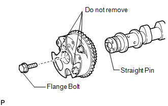 Do
not loosen or remove the 3 bolts shown in the illustration. If any of
them are loosened or removed, the backlash of the gear in the timing
tube will go out of adjustment. In this case, replace the camshaft
timing gear assembly with a new one.
Do
not loosen or remove the 3 bolts shown in the illustration. If any of
them are loosened or removed, the backlash of the gear in the timing
tube will go out of adjustment. In this case, replace the camshaft
timing gear assembly with a new one.
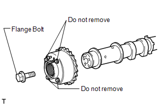 Do
not loosen or remove the 4 bolts shown in the illustration. If any of
them are loosened or removed, the backlash of the gear in the timing
tube will go out of adjustment. In this case, replace the camshaft
timing exhaust gear assembly with a new one.
Do
not loosen or remove the 4 bolts shown in the illustration. If any of
them are loosened or removed, the backlash of the gear in the timing
tube will go out of adjustment. In this case, replace the camshaft
timing exhaust gear assembly with a new one.