INSTALLATION PROCEDURE 1. INSTALL NOISE FILTER (a) RH Side: Install the noise filter to the cylinder head cover with the bolt. Torque: 10 N·m {102 kgf·cm, 7 ft·lbf} (b) LH Side: Install the noise filter to the cylinder head cover with the bolt. Torque: 10 N·m {102 kgf·cm, 7 ft·lbf} 2. INSTALL IGNITION COIL ASSEMBLY (a) Install the 8 ignition coils with the 8 bolts. Torque: 10 N·m {102 kgf·cm, 7 ft·lbf} 3. INSTALL KNOCK SENSOR 4. INSTALL NO. 11 WATER BY-PASS HOSE
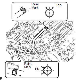
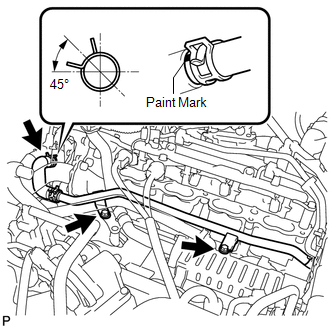
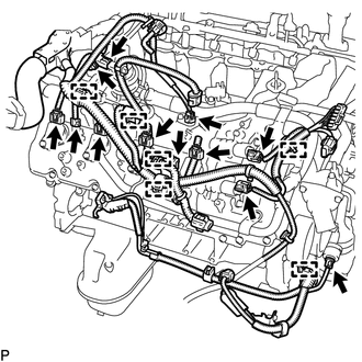
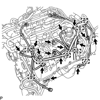
5. INSTALL ENGINE WIRE 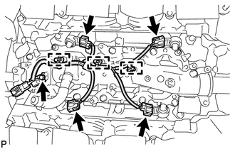 (a) Connect the 3 clamps and 4 knock sensor connectors to install the engine wire. 6. INSTALL NO. 1 ENGINE COVER
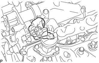
7. INSTALL NO. 2 ENGINE COVER
8. INSTALL SEPARATOR CASE 9. INSTALL NO. 1 IDLER PULLEY SUB-ASSEMBLY 10. INSTALL WATER PUMP PULLEY 11. INSTALL FRONT WATER BY-PASS JOINT 12. INSTALL WATER INLET HOUSING 13. INSTALL WATER BY-PASS PIPE SUB-ASSEMBLY 14. INSTALL AIR TUBE SUB-ASSEMBLY RH 15. INSTALL NO. 1 WATER BY-PASS HOSE 16. INSTALL NO. 3 ENGINE COVER 17. INSTALL NO. 4 ENGINE COVER 18. INSTALL OIL PRESSURE SENDER GAUGE ASSEMBLY 19. INSTALL FUEL DELIVERY PIPE SUB-ASSEMBLY RH 20. INSTALL FUEL DELIVERY PIPE SUB-ASSEMBLY LH 21. INSTALL FRONT NO. 1 ENGINE MOUNTING BRACKET LH 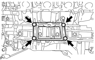 (a) Install the mounting bracket with the 4 bolts. Torque: 35 N·m {357 kgf·cm, 26 ft·lbf} 22. INSTALL FRONT NO. 1 ENGINE MOUNTING BRACKET RH 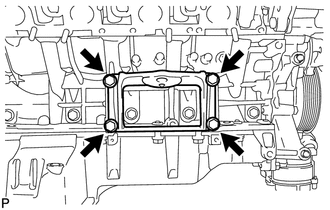 (a) Install the mounting bracket with the 4 bolts. Torque: 35 N·m {357 kgf·cm, 26 ft·lbf} 23. INSTALL FRONT ENGINE MOUNTING INSULATOR RH
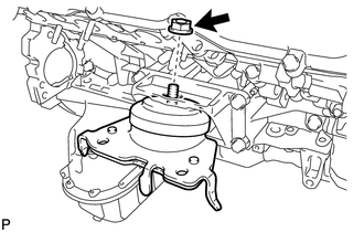
24. INSTALL FRONT ENGINE MOUNTING INSULATOR LH
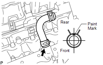
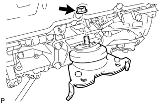
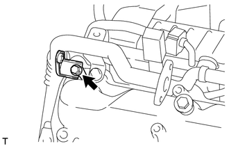
25. INSTALL CYLINDER BLOCK WATER DRAIN COCK SUB-ASSEMBLY 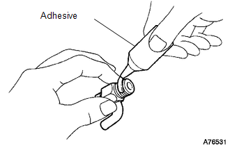 (a) Apply adhesive to 2 or 3 threads of the drain cocks. Adhesive: Toyota Genuine Adhesive 1344, Three Bond 1344 or equivalent 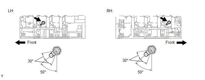 (b) Install the water drain cocks. Torque: 30 N·m {306 kgf·cm, 22 ft·lbf} (c) Tighten the drain cocks up to an additional 360° so that the drain cock pipes are within the range shown in the illustration. NOTICE:
(d) Install the water drain cock plugs to the water drain cocks. Torque: 13 N·m {130 kgf·cm, 9 ft·lbf} 26. INSTALL EGR COOLER ASSEMBLY 27. CONNECT NO. 11 WATER BY-PASS HOSE 28. INSTALL NO. 8 WATER BY-PASS HOSE
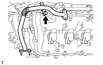
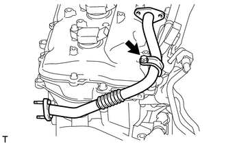
29. INSTALL NO. 3 WATER BY-PASS PIPE SUB-ASSEMBLY
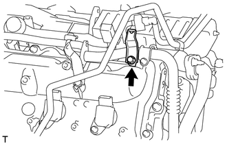
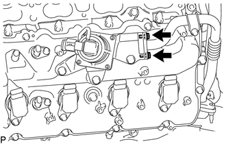
30. INSTALL NO. 3 AIR TUBE
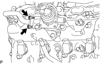
31. INSTALL NO. 4 AIR TUBE
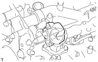
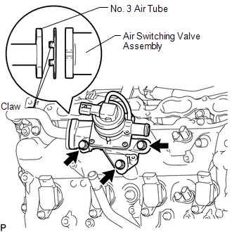
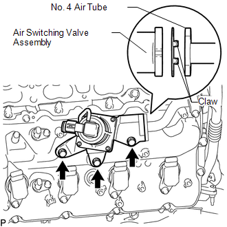
32. INSTALL AIR SWITCHING VALVE ASSEMBLY (for Bank 2)
33. INSTALL AIR SWITCHING VALVE ASSEMBLY (for Bank 1)
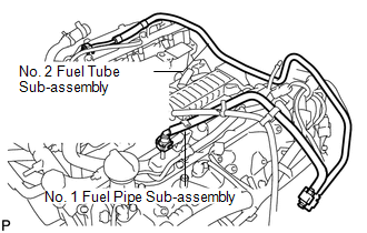
34. INSTALL NO. 2 FUEL TUBE SUB-ASSEMBLY
35. INSTALL NO. 1 FUEL PIPE SUB-ASSEMBLY (a) Install the No. 1 fuel pipe (See page
36. INSTALL ENGINE WIRE 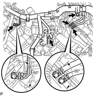 (a) Engine Rear Side: (1) Install the 4 bolts. Torque: 8.4 N·m {86 kgf·cm, 74 in·lbf} (2) Connect the clamp and connector.
|
Toyota Tundra Service Manual > Generator: Removal
REMOVAL PROCEDURE 1. PRECAUTION NOTICE: After turning the ignition switch off, waiting time may be required before disconnecting the cable from the battery terminal. Therefore, make sure to read the disconnecting the cable from the battery terminal notice before proceeding with work (See page ). 2. ...