Toyota Tundra Service Manual: Pressure Control Solenoid "B" Electrical (Shift Solenoid Valve SL2) (P0778)

Toyota Tundra Service Manual / Engine, Hybrid System / A760e Automatic Transmission / Transaxle / Automatic Transmission System / Pressure Control Solenoid "B" Electrical (Shift Solenoid Valve SL2) (P0778)

DESCRIPTION

Shifting from 1st to 6th is performed in combination with the ON and OFF operation of the shift solenoid valves SL1, SL2, S1, S2, S3, S4 and SR, which are controlled by the ECM. If an open or short circuit occurs in the shift solenoid valves, the ECM controls the remaining normal shift solenoid valves to allow the vehicle to be operated safely (See page ).

DTC Code

DTC Detection Condition

Trouble Area

P0778

The ECM checks for an open or short in the shift solenoid valve SL2 circuit while driving and shifting gears (1-trip detection logic).

Output signal duty equals 100%.

HINT:

SL2 output signal duty is less than 100% under normal conditions.

  • Open or short in shift solenoid valve SL2 circuit
  • Shift solenoid valve SL2
  • ECM

MONITOR DESCRIPTION

This DTC indicates an open or short in the shift solenoid valve SL2 circuit. The ECM commands gear shifts by turning the shift solenoid valves ON/OFF. When there is an open or short circuit in any shift solenoid valve circuit, the ECM detects the problem, illuminates the MIL and stores the DTC. Also, the ECM performs the fail-safe function and turns the other normal shift solenoid valves ON/OFF. In case of an open or short circuit, the ECM stops sending current to the open or short-circuited solenoid.

While driving and shifting gears, if the ECM detects an open or short in the shift solenoid valve SL2 circuit, the ECM determines there is a malfunction (See page ).

MONITOR STRATEGY

Related DTCs

P0778: Shift solenoid valve SL2/Range check

Required sensors/Components

Shift solenoid valve SL2

Frequency of operation

Continuous

Duration

1 second

MIL operation

Immediately

Sequence of operation

None

TYPICAL ENABLING CONDITIONS

The monitor will run whenever the following DTCs are not present

None

Solenoid current cut status

Not cut

Battery voltage

11 V or more

Ignition switch

ON

Starter

OFF

TYPICAL MALFUNCTION THRESHOLDS

Solenoid status from solenoid driver MIC

Fail

COMPONENT OPERATING RANGE
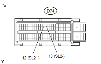
Output signal duty

Less than 100%

WIRING DIAGRAM

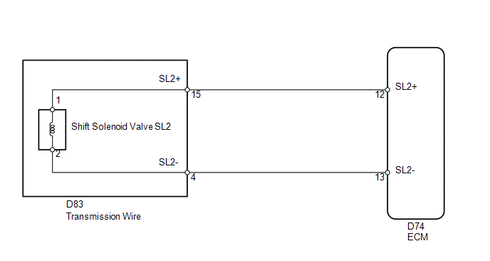
CAUTION / NOTICE / HINT

NOTICE:

Perform the universal trip to clear permanent DTCs (See page ).

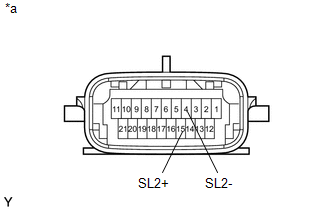
HINT:

The shift solenoid valve SL2 is turned ON/OFF normally when the shift lever is in D:

ECM gear shift command

1st

2nd

3rd

4th

5th

6th

Shift solenoid valve SL2

ON

ON

ON

ON

OFF

OFF

PROCEDURE

1.

INSPECT TRANSMISSION WIRE (SHIFT SOLENOID VALVE SL2)

(a) Disconnect the D83 transmission wire connector.

(b) Measure the resistance according to the value(s) in the table below.

Standard Resistance:

Tester Connection

Condition

Specified Condition

15 (SL2+) - 4 (SL2-)

20°C (68°F)

5.0 to 5.6 Ω

15 (SL2+) - Body ground

Always

10 kΩ or higher

4 (SL2-) - Body ground

Always

10 kΩ or higher

Text in Illustration

*a

Component without harness connected

(Transmission Wire)

NG

GO TO STEP 3

OK

2.

CHECK HARNESS AND CONNECTOR (TRANSMISSION WIRE - ECM)

(a) Disconnect the D74 ECM connector.

(b) Measure the resistance according to the value(s) in the table below.

Standard Resistance:

Tester Connection

Condition

Specified Condition

D74-12 (SL2+) - D74-13 (SL2-)

20°C (68°F)

5.0 to 5.6 Ω

D74-12 (SL2+) - Body ground

Always

10 kΩ or higher

D74-13 (SL2-) - Body ground

Always

10 kΩ or higher

Text in Illustration

*a

Front view of wire harness connector

(to ECM)

OK

REPLACE ECM

NG

REPAIR OR REPLACE HARNESS OR CONNECTOR

3.

INSPECT SHIFT SOLENOID VALVE SL2

OK

REPAIR OR REPLACE TRANSMISSION WIRE

NG

REPLACE SHIFT SOLENOID VALVE SL2

    Shift Solenoid "D" Performance (Shift Solenoid Valve S4) (P0766,P0776)

    1-2 Shift (1-2 Shift Valve) (P0781)

    See More:

    Toyota Tundra Service Manual > Audio / Video: Microphone Amplifier
    ComponentsCOMPONENTS ILLUSTRATION *A for Double Cab - - *1 TELEPHONE MICROPHONE ASSEMBLY - - ILLUSTRATION *A for CrewMax *B w/o Sliding Roof *C w/ Sliding Roof - - *1 TELEPHONE MICROPHONE ASSEMBLY - - InstallationINSTALLATION PROCEDURE 1. INSTALL TELEPHONE MICROPHONE ASSEMBLY (a) Attach the 2 claws ...

    Toyota Tundra Owners Manual

    Toyota Tundra Service Manual

    © 2024 Copyright www.ttundra.com
    0.0105