DISASSEMBLY PROCEDURE 1. REMOVE SHIFT LEVER CAP
2. REMOVE UPPER POSITION INDICATOR HOUSING
3. REMOVE POSITION INDICATOR SLIDE COVER
4. REMOVE NO. 2 POSITION INDICATOR SLIDE COVER
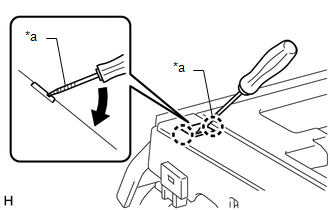
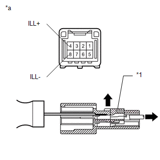
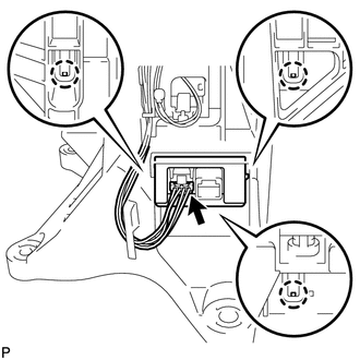
5. DISCONNECT INDICATOR LIGHT WIRE SUB-ASSEMBLY
(b) Using a thin-bladed screwdriver, pull out the 4 (ILL+) and 8 (ILL-) terminals from the rear as shown in the illustration.
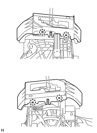
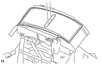
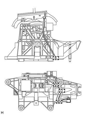
6. REMOVE LOWER POSITION INDICATOR HOUSING
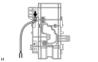
7. REMOVE INDICATOR LIGHT WIRE SUB-ASSEMBLY
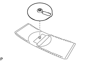
8. REMOVE POSITION INDICATOR LED
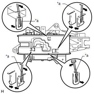
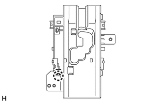
9. REMOVE SHIFT LOCK CONTROL ECU
(b) Detach the 3 claws and remove the shift lock control ECU from the shift lever assembly. |
Toyota Tundra Service Manual > Power Tilt And Power Telescopic Steering Column System: Data List / Active Test
DATA LIST / ACTIVE TEST 1. READ DATA LIST HINT: Using the Techstream to read the Data List allows the values or states of switches, sensors, actuators and other items to be read without removing any parts. This non-intrusive inspection can be very useful because intermittent conditions or signals ma ...