Components COMPONENTS ILLUSTRATION 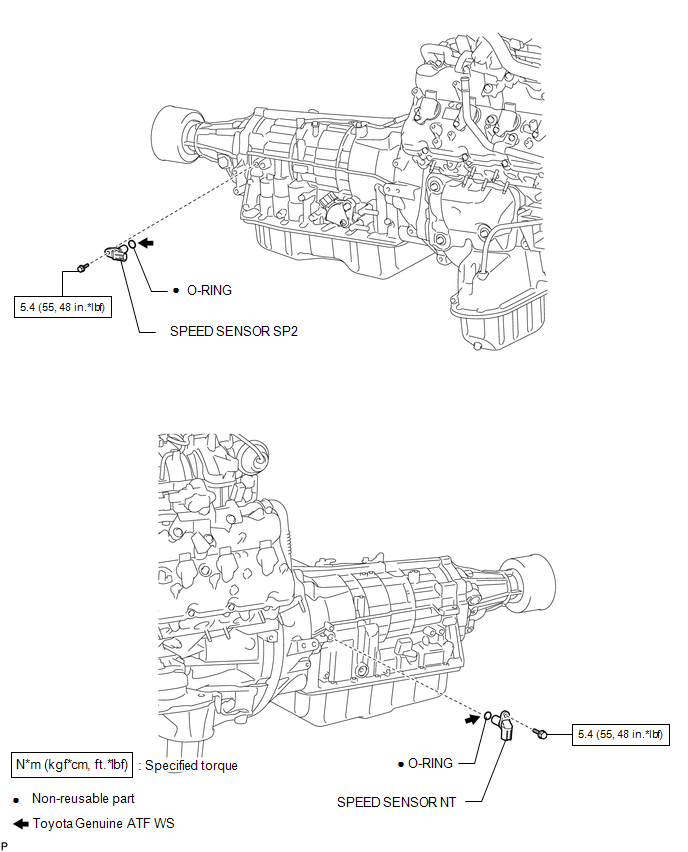 Inspection INSPECTION PROCEDURE 1. INSPECT SPEED SENSOR NT 
(a) Measure the resistance according to the value(s) in the table below. Standard Resistance:
If the result is not as specified, replace the sensor. 2. INSPECT SPEED SENSOR SP2 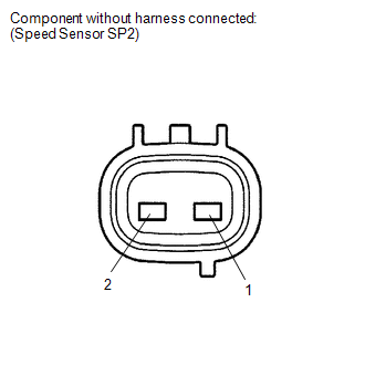
(a) Measure the resistance according to the value(s) in the table below. Standard Resistance:
If the result is not as specified, replace the sensor. Installation INSTALLATION PROCEDURE 1. INSTALL SPEED SENSOR SP2 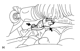
(a) Coat a new O-ring with ATF and install it to the sensor. (b) Install the sensor with the bolt. Torque: 5.4 N·m {55 kgf·cm, 48 in·lbf} (c) Connect the sensor connector. 2. INSTALL SPEED SENSOR NT 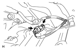
(a) Coat a new O-ring with ATF and install it to the sensor. (b) Install the sensor with the bolt. Torque: 5.4 N·m {55 kgf·cm, 48 in·lbf} (c) Connect the sensor connector. Removal REMOVAL PROCEDURE 1. REMOVE SPEED SENSOR NT  (a) Disconnect the sensor connector. (b) Remove the bolt and sensor. (c) Remove the O-ring from the sensor. 2. REMOVE SPEED SENSOR SP2  (a) Disconnect the sensor connector. (b) Remove the bolt and sensor. (c) Remove the O-ring from the sensor. |
Toyota Tundra Service Manual > Cargo Light Switch: Inspection
INSPECTION PROCEDURE 1. INSPECT DECK LIGHT SWITCH ASSEMBLY (a) Check the resistance. (1) Measure the resistance according to the value(s) in the table below. Standard Resistance: Tester Connection Switch Condition Specified Condition 5 (CCTY) - 9 (CGON) Cargo light switch ON Below 1 Ω Cargo light s ...


