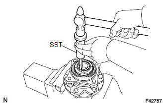
DISASSEMBLY CAUTION / NOTICE / HINT NOTICE: Do not allow foreign matter, etc. to contact the ABS rotor bearing. PROCEDURE 1. REMOVE FRONT WHEEL ADJUSTING NUT (for 2WD)
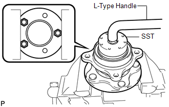
(b) Install a nut to the front axle hub, and fix it in a vise.
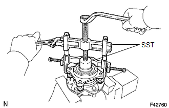
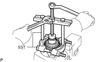
2. REMOVE FRONT AXLE WITH ABS ROTOR BEARING ASSEMBLY
(b) Using SST, remove the bearing. SST: 09950-40011 09951-04020 09952-04010 09953-04020 09954-04010 09955-04061 09957-04010 09958-04011 SST: 09950-60010 09951-00550
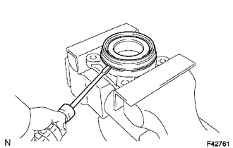
3. REMOVE FRONT AXLE HUB OIL SEAL
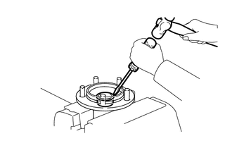
4. REMOVE PLUG (for 2WD)
|
Toyota Tundra Service Manual > Tire Pressure Warning System: Registration
REGISTRATION PROCEDURE 1. BEFORE REGISTRATION NOTICE: The transmitter ID is written on the tire pressure warning valve and transmitter. It is not possible to read the transmitter ID after installing the tire onto the wheel. Therefore, make a note of the transmitter ID before installing the tire. Tir ...