REMOVAL CAUTION / NOTICE / HINT HINT:
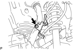
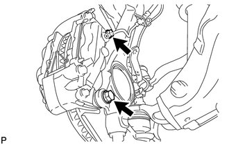
PROCEDURE 1. REMOVE FRONT WHEEL 2. DISCONNECT FRONT DISC BRAKE CALIPER ASSEMBLY LH
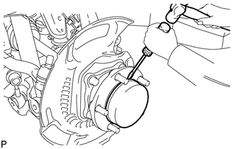
3. REMOVE FRONT DISC LH 4. REMOVE FRONT AXLE HUB GREASE CAP LH (for 4WD)
5. REMOVE FRONT AXLE HUB NUT LH (for 4WD)
(b) Using a 39 mm socket wrench, remove the axle hub nut. 6. REMOVE FRONT AXLE HUB SUB-ASSEMBLY LH (for 2WD)
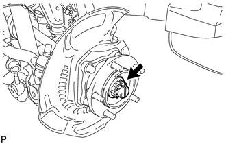
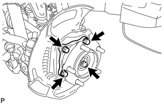
(b) Remove the axle hub and dust cover from the steering knuckle. (c) Remove the O-ring from the axle hub. 7. REMOVE FRONT AXLE HUB SUB-ASSEMBLY LH (for 4WD)
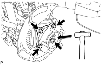
(b) Using a plastic-faced hammer, tap out the front drive shaft from the front axle hub. NOTICE: Be careful not to damage the drive shaft boot. (c) Remove the axle hub and dust cover from the steering knuckle. (d) Remove the O-ring from the axle hub. |
Toyota Tundra Service Manual > Can Communication System: Open in Bus 4 Main Bus Line
DESCRIPTION There may be an open circuit in one of the CAN main bus lines when the resistance between terminals 22 (CA2H) and 7 (CA2L) of the central gateway ECU (network gateway ECU) is 70 Ω or higher. Symptom Trouble Area Resistance between terminals 22 (CA2H) and 7 (CA2L) of the central gateway ...