PARTS LOCATION ILLUSTRATION 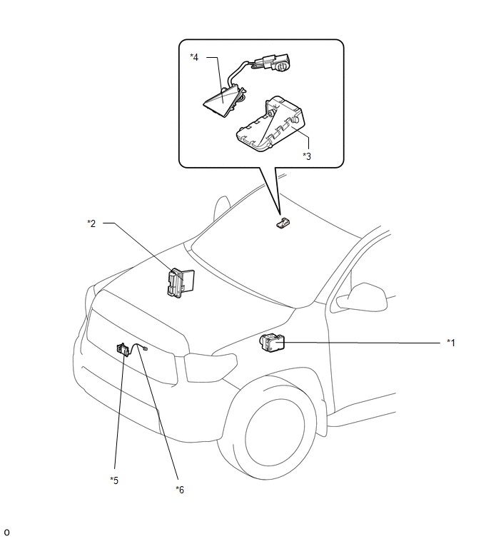
ILLUSTRATION 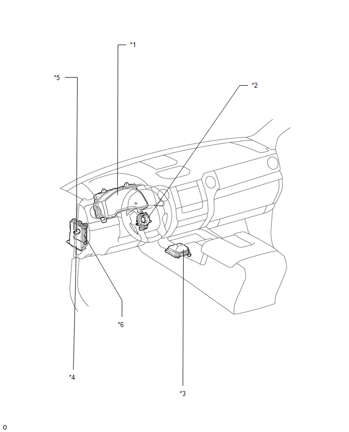
|
Toyota Tundra Service Manual > Power Door Lock Control System: All Doors LOCK/UNLOCK Functions do not Operate Via Door Key Cylinder
DESCRIPTION The main body ECU (multiplex network body ECU) receives driver door key cylinder lock or unlock switch signals from the front door lock assembly LH. The main body ECU (multiplex network body ECU) activates the door lock motor on each door according to these signals. WIRING DIAGRAM CAUTIO ...


