DESCRIPTION The forward recognition camera receives a lane departure alert switch signal from the steering pad switch assembly. WIRING DIAGRAM 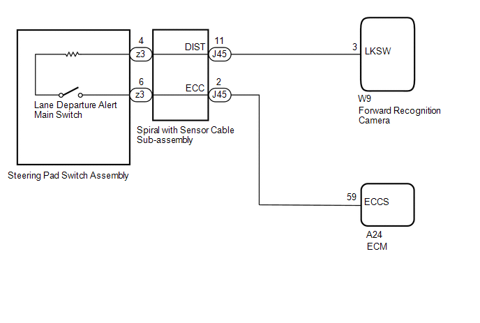 CAUTION / NOTICE / HINT NOTICE: The vehicle is equipped with a Supplemental Restraint System (SRS) which includes components such as airbags. Before servicing (including removal or installation of parts), be sure to read the precaution for Supplemental Restraint System. Click here PROCEDURE
(a) Remove the steering pad switch assembly. Click here (b) Inspect the steering pad switch assembly. Click here
(a) Remove the spiral with sensor cable sub-assembly. Click here
(b) Inspect the spiral with sensor cable sub-assembly. Click here
(a) Disconnect the J45 spiral with sensor cable sub-assembly connector. (b) Disconnect the W9 forward recognition camera connector. (c) Measure the resistance according to the value(s) in the table below. Standard Resistance:
(d) Connect the W9 forward recognition camera connector. (e) Connect the J45 spiral with sensor cable sub-assembly connector.
(a) Disconnect the J45 spiral with sensor cable sub-assembly connector. (b) Disconnect the A24 ECM connector. (c) Measure the resistance according to the value(s) in the table below. Standard Resistance:
(d) Connect the J45 spiral with sensor cable sub-assembly connector. (e) Connect the A24 ECM connector.
|
Toyota Tundra Service Manual > Front Axle Hub: Removal
REMOVAL CAUTION / NOTICE / HINT HINT: Use the same procedures for the LH side and RH side. The procedures listed below are for the LH side. PROCEDURE 1. REMOVE FRONT WHEEL 2. DISCONNECT FRONT DISC BRAKE CALIPER ASSEMBLY LH (a) Remove the bolt and disconnect the brake tube bracket from the steering k ...


