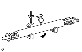
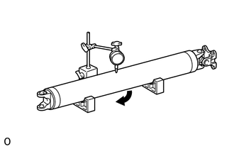
INSPECTION CAUTION / NOTICE / HINT PROCEDURE 1. INSPECT PROPELLER SHAFT WITH CENTER BEARING ASSEMBLY
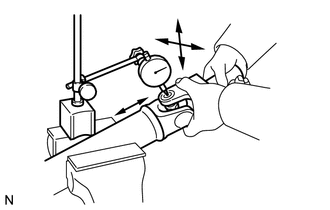
2. INSPECT PROPELLER SHAFT UNIVERSAL JOINT SPIDER BEARING
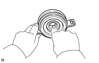
(b) Inspect the spider bearing for wear or damage. (c) Using a dial indicator, measure the spider bearing axial play by turning the yoke of the flange while holding the shaft tightly. Maximum bearing axial play: 0.05 mm (0.00197 in.) If the spider bearing axial play is more than the maximum, replace the spider bearing. 3. INSPECT NO. 1 CENTER SUPPORT BEARING ASSEMBLY
|
Toyota Tundra Service Manual > Trailer Brake Control System: Stop Light Control Relay Malfunction (C1380)
DESCRIPTION The skid control ECU (brake actuator assembly) sends a stop light operation request signal to the stop light control relay. If the skid control ECU (brake actuator assembly) detects a malfunction in the stop light control relay circuit, the trailer brake control ECU (brake control with b ...