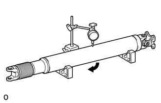
INSPECTION CAUTION / NOTICE / HINT PROCEDURE 1. INSPECT PROPELLER SHAFT WITH CENTER BEARING ASSEMBLY 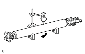 (a) Using a dial indicator, measure the intermediate shaft runout. Maximum runout: 0.61 mm (0.0240 in.)
2. INSPECT REAR PROPELLER SHAFT UNIVERSAL JOINT SPIDER BEARING 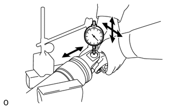 (a) Mount the propeller shaft in a vise. NOTICE: Be careful not to grip the propeller shaft tube too tightly in a vise as this will cause deformation. (b) Inspect the spider bearing for wear or damage. (c) Using a dial indicator, measure the spider bearing axial play by turning the yoke of the flange while holding the shaft tightly. Maximum runout: 0.05 mm (0.00197 in.)
3. INSPECT NO. 1 CENTER SUPPORT BEARING ASSEMBLY 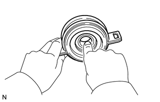 (a) Check that the bearing turns freely.
|
Toyota Tundra Service Manual > Tire And Wheel System: How To Proceed With Troubleshooting
PROCEDURE 1. CHECK TIRE AND WHEEL SYSTEM DIAGNOSIS OF IRREGULAR TIRE WEAR GO TO STEP 9 DIAGNOSIS OF TIRE VIBRATION 2. TIGHTEN WHEEL NUTS NEXT 3. INSPECT TIRES Click here NG GO TO STEP 6 OK 4. INSPECT AND/OR ADJUST WHEEL BALANCE Click here NEXT 5. INSPECT FRONT AXLE HUB BEARING LOOSENESS AND AXLE HUB ...