Toyota Tundra Service Manual: Parts Location

PARTS LOCATION

ILLUSTRATION
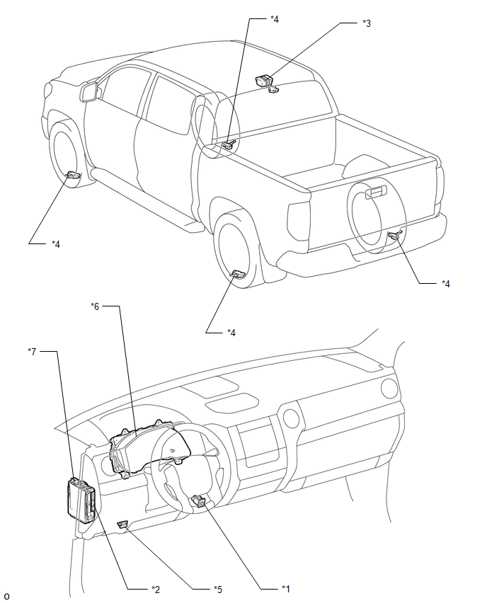
*1

TIRE PRESSURE WARNING RESET SWITCH

*2

MAIN BODY ECU (MULTIPLEX NETWORK BODY ECU)

*3

TIRE PRESSURE WARNING ECU AND RECEIVER

*4

TIRE PRESSURE WARNING VALVE AND TRANSMITTER

*5

DLC3

*6

COMBINATION METER ASSEMBLY

- TIRE PRESSURE WARNING LIGHT

*7

DRIVER SIDE JUNCTION BLOCK ASSEMBLY

- ECU-B NO.2 FUSE

-

-

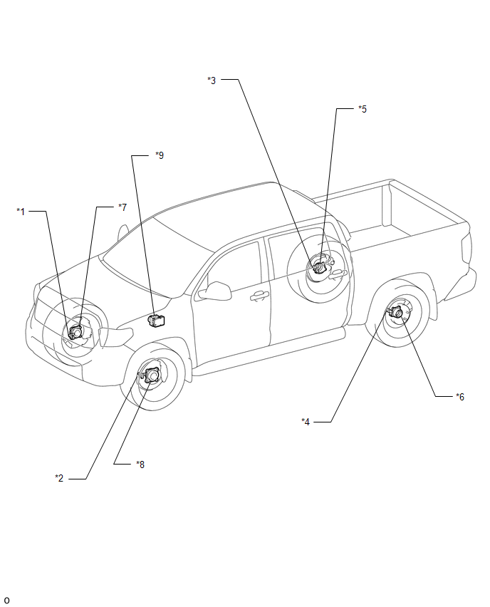
ILLUSTRATION

*1

FRONT SPEED SENSOR RH

*2

FRONT SPEED SENSOR LH

*3

REAR SPEED SENSOR RH

*4

REAR SPEED SENSOR LH

*5

REAR AXLE HUB AND BEARING ASSEMBLY RH

*6

REAR AXLE HUB AND BEARING ASSEMBLY LH

*7

FRONT AXLE WITH ABS ROTOR BEARING ASSEMBLY RH

*8

FRONT AXLE WITH ABS ROTOR BEARING ASSEMBLY LH

*9

SKID CONTROL ECU (BRAKE ACTUATOR ASSEMBLY)

-

-

    Operation Check

    Precaution

    See More:

    Toyota Tundra Service Manual > Blind Spot Monitor System: Destination Information Undefined (C1AB8)
    DESCRIPTION This DTC is stored when correct destination information is not sent from the main body ECU (multiplex network body ECU) and destination information cannot be confirmed after a blind spot monitor sensor has been replaced. DTC No. DTC Detection Condition Trouble Area C1AB8 The blind spot m ...

    Toyota Tundra Owners Manual

    Toyota Tundra Service Manual

    © 2026 Copyright www.ttundra.com
    0.0114