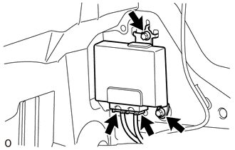
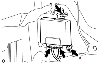
Components COMPONENTS ILLUSTRATION 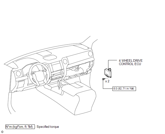 Installation INSTALLATION PROCEDURE 1. INSTALL 4 WHEEL DRIVE CONTROL ECU (a) Connect the 2 connectors.
2. INSTALL CLEARANCE WARNING ECU WITH BRACKET (See page
3. INSTALL LOWER INSTRUMENT PANEL FINISH PANEL SUB-ASSEMBLY RH
4. CONNECT CABLE TO NEGATIVE BATTERY TERMINAL NOTICE: When disconnecting the cable, some systems need to be initialized after the cable is reconnected (See page
Removal REMOVAL PROCEDURE 1. PRECAUTION NOTICE: After
turning the ignition switch off, waiting time may be required before
disconnecting the cable from the negative (-) battery terminal.
Therefore, make sure to read the disconnecting the cable from the
negative (-) battery terminal notice before proceeding with work (See
page 2. DISCONNECT CABLE FROM NEGATIVE BATTERY TERMINAL NOTICE: When disconnecting the cable, some systems need to be initialized after the cable is reconnected (See page
3. REMOVE LOWER INSTRUMENT PANEL FINISH PANEL SUB-ASSEMBLY RH
4. REMOVE CLEARANCE WARNING ECU WITH BRACKET (See page
5. REMOVE 4 WHEEL DRIVE CONTROL ECU
(b) Remove the 2 bolts and 4 wheel drive control ECU. NOTICE:
|
Toyota Tundra Service Manual > Vehicle Stability Control System: How To Proceed With Troubleshooting
CAUTION / NOTICE / HINT HINT: *: Use the Techstream. PROCEDURE 1. VEHICLE BROUGHT TO WORKSHOP NEXT 2. CUSTOMER PROBLEM ANALYSIS (a) Interview the customer and confirm the problem. Click here NEXT 3. CHECK DTC AND FREEZE FRAME DATA* (a) Check and record DTCs and Freeze Frame Data. for DTC Check / Cle ...

 )
)