DESCRIPTION This DTC is detected when a short to B+ is detected in the solenoid coil drive circuit.
WIRING DIAGRAM Refer to DTCs P17A5 and P17A6 (See page PROCEDURE
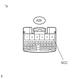 (a) Disconnect the 4 wheel drive control ECU connector. (b) Measure the voltage according to the value(s) in the table below. Standard Voltage:
(a) Disconnect the A26 4 wheel drive control ECU connector. (b) Disconnect the D67 transfer shift actuator assembly connector. (c) Measure the voltage according to the value(s) in the table below. Standard Voltage:
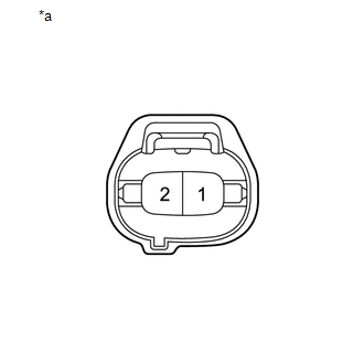 (a) Disconnect the A solenoid coil sub-assembly connector. (b) Measure the voltage according to the value(s) in the table below. Standard Voltage:
|
Toyota Tundra Service Manual > Front Propeller Shaft Assembly: Inspection
INSPECTION PROCEDURE 1. INSPECT FRONT PROPELLER SHAFT ASSEMBLY (a) Check that the propeller shaft is not damaged or deformed. If necessary, replace the propeller shaft. (b) Using a dial indicator, check the propeller shaft runout. Maximum runout: 0.61 mm (0.0240 in.) 2. INSPECT UNIVERSAL JOINT SPIDE ...

 ).
).


