DESCRIPTION This DTC is detected if the transfer position switch 2-4 terminal and LO terminal signals are simultaneously received. |
DTC Code | DTC Detection Condition
- Diagnosis Condition
- Malfunction Status
- Malfunction Time
- Other
| Trouble Area | |
P279E |
- Ignition switch is ON and engine is running
- 2-4 terminal signal is OFF (OPEN) and LO terminal signal is OFF (OPEN)
- 60 seconds or more
- 1 trip detection logic
|
- Wire harness and connector
- 4 wheel drive control ECU
- Transfer position switch
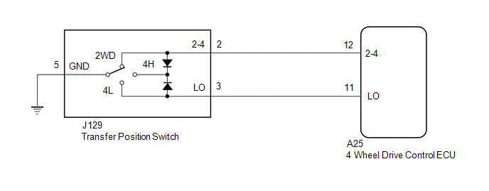
| WIRING DIAGRAM
 PROCEDURE
| 1. |
CHECK HARNESS AND CONNECTOR (4 WHEEL DRIVE CONTROL ECU - TRANSFER POSITION SWITCH) |
(a) Disconnect the A25 4 wheel drive control ECU connector. (b) Disconnect the J129 transfer position switch connector.
(c) Measure the resistance according to the value(s) in the table below.
Standard Resistance: |
Tester Connection | Condition |
Specified Condition | |
A25-12 (2-4) - J129-2 (2-4) |
Always | Below 1 Ω | |
A25-11 (LO) - J129-3 (LO) |
Always | Below 1 Ω | |
J129-5 (GND) - Body ground |
Always | Below 1 Ω | |
A25-12 (2-4) or J129-2 (2-4) - Body ground |
Always | 10 kΩ or higher | |
A25-11 (LO) or J129-3 (LO) - Body ground |
Always | 10 kΩ or higher | |
A25-12 (2-4) or J129-2 (2-4) - A25-11 (LO) or J129-3 (LO) |
Always | 10 kΩ or higher |
| NG |
 | REPAIR OR REPLACE HARNESS OR CONNECTOR |
|
OK |
 | |
| 2. |
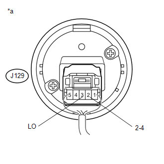
CHECK TRANSFER POSITION SWITCH | (a) Remove the transfer position switch with its connector still connected (See page
 ). ).
 (b) Measure the voltage according to the value(s) in the table below.
Standard Voltage: |
Tester Connection | Switch Condition |
Specified Condition | |
J129-2 (2-4) - Body ground |
Ignition switch ON 2WD position |
Below 1 V | |
Ignition switch ON 4H position |
Below 1.5 V | |
Ignition switch ON 4L position |
10.5 to 14 V | |
J129-3 (LO) - Body ground |
Ignition switch ON 2WD position |
10.5 to 14 V | |
Ignition switch ON 4H position |
Below 1.5 V | |
Ignition switch ON 4L position |
Below 1 V | Text in Illustration |
*a | Component with harness connected
(Transfer Position Switch) |
| OK |
| REPLACE 4 WHEEL DRIVE CONTROL ECU |
| NG |
| REPLACE TRANSFER POSITION SWITCH | | 

