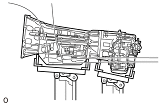
INSTALLATION CAUTION / NOTICE / HINT CAUTION: Be sure to perform this procedure with several people as the transfer assembly is very heavy. PROCEDURE 1. INSTALL TRANSFER ASSEMBLY
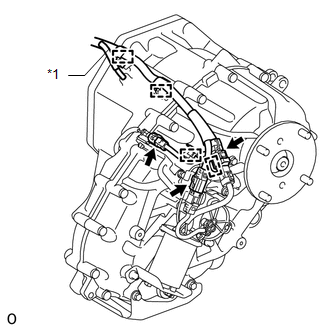
(b) Raise the transfer assembly so that it is level with the automatic transmission assembly and install the transfer assembly with the 8 bolts. Torque: 40 N·m {408 kgf·cm, 30 ft·lbf} NOTICE: Take care not to damage the rear adaptor oil seal with the transfer input shaft spline. 2. CONNECT WIRE HARNESS AND CONNECTOR
3. INSTALL REAR NO. 1 ENGINE MOUNTING INSULATOR (a) Remove the transmission jack from the transfer assembly. NOTICE: Do not remove the transmission jack from the automatic transmission assembly in this step. (b) Install the rear No. 1 engine mounting insulator with the 4 bolts. Torque: 59 N·m {602 kgf·cm, 44 ft·lbf} 4. INSTALL NO. 3 FRAME CROSSMEMBER SUB-ASSEMBLY (a) Install the No. 3 frame crossmember sub-assembly to the rear No. 1 engine mounting insulator with the 4 bolts. Torque: 21 N·m {214 kgf·cm, 15 ft·lbf} (b) Install the No. 3 frame crossmember sub-assembly with the 4 bolts, 4 washers and 4 nuts. Torque: 110 N·m {1122 kgf·cm, 81 ft·lbf} NOTICE: Install the bolt from the front of the vehicle, install the washer and nut to the bolt, and then tighten the nut. (c) Remove the transmission jack from the automatic transmission assembly. 5. INSTALL PROPELLER WITH CENTER BEARING SHAFT ASSEMBLY (See page
6. INSTALL FRONT PROPELLER SHAFT ASSEMBLY (See page 7. ADD TRANSFER OIL 8. CHECK TRANSFER OIL
9. CHECK FOR TRANSFER OIL LEAK |
Toyota Tundra Service Manual > Hazard Warning Switch: Inspection
INSPECTION PROCEDURE 1. INSPECT AIR CONDITIONING CONTROL ASSEMBLY (HAZARD WARNING SWITCH) (a) Measure the resistance according to the value(s) in the table below. Standard Resistance: Tester Connection Switch Condition Specified Condition 1 (HAZ) - 5 (GND) Hazard warning switch off 10 kΩ or higher ...