PARTS LOCATION ILLUSTRATION 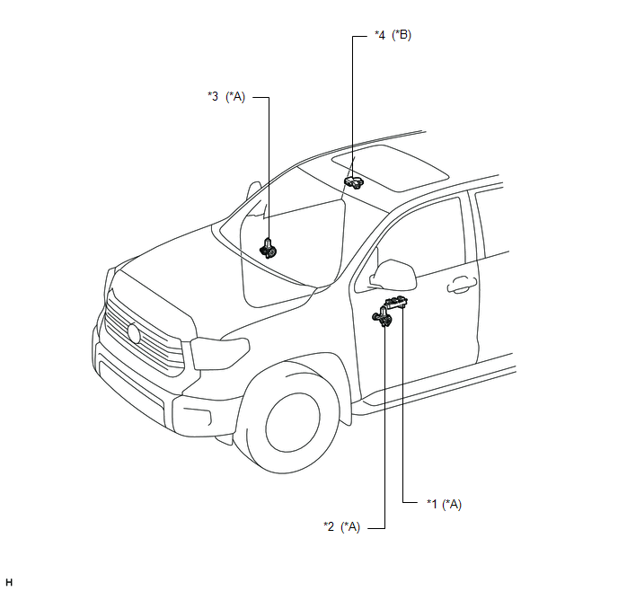
ILLUSTRATION 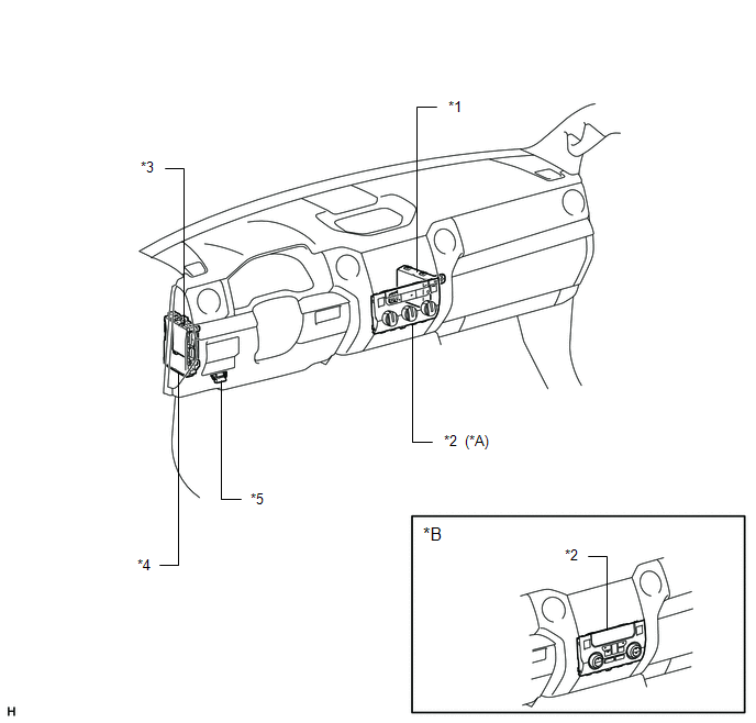
|
Toyota Tundra Service Manual > Hood: Adjustment
ADJUSTMENT CAUTION / NOTICE / HINT HINT: Centering bolts are used to mount the hood hinge and hood lock. The hood and hood lock cannot be adjusted with the centering bolts on. Substitute the centering bolts with standard bolts (with washers) when making adjustments. A bolt without a torque specifica ...


