TERMINALS OF ECU 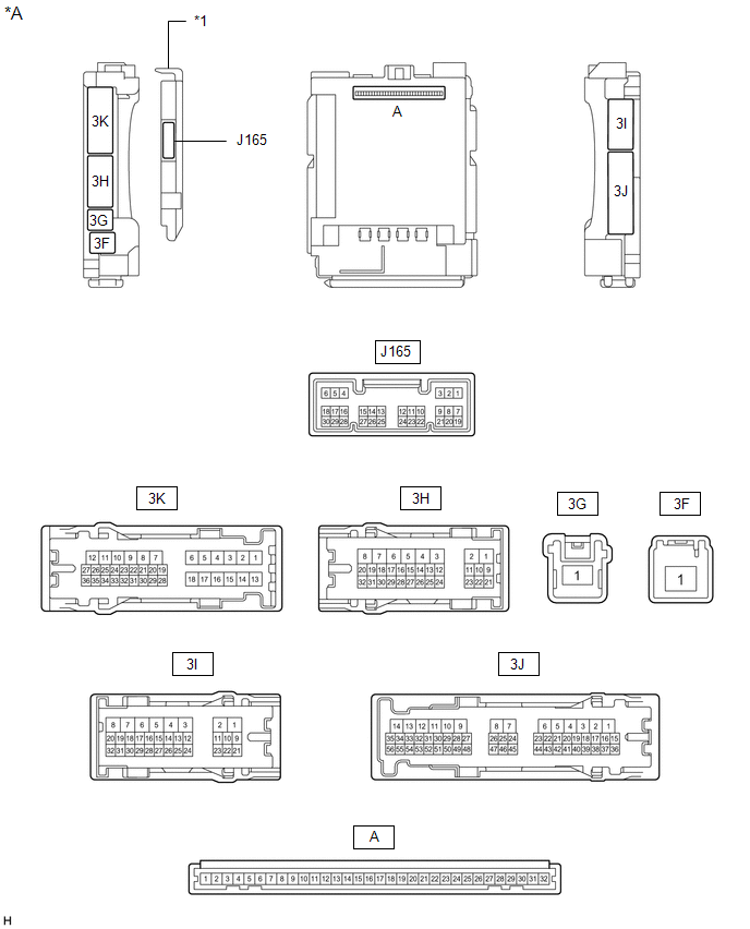
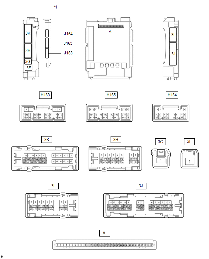
1. CHECK DRIVER SIDE JUNCTION BLOCK ASSEMBLY AND MAIN BODY ECU (MULTIPLEX NETWORK BODY ECU) (a) Remove the main body ECU (multiplex network body ECU) from the driver side junction block assembly. Click here (b) Connect the driver side junction block assembly connectors. (c) Measure the voltage and resistance according to the value(s) in the table below.
(d) Install the main body ECU (multiplex network body ECU) to the driver side junction block assembly. Click here (e) Measure the pulse according to the value(s) in the table below.
2. CHECK POWER WINDOW REGULATOR MASTER SWITCH ASSEMBLY (for Power Window Control System [w/ Jam Protection Function])  (a) Disconnect the N2 power window regulator master switch assembly connector. (b) Measure the voltage and resistance according to the value(s) in the table below.
3. CHECK FRONT POWER WINDOW REGULATOR MOTOR ASSEMBLY LH (for Power Window Control System [w/ Jam Protection Function])  (a) Disconnect the N12 front power window regulator motor assembly LH connector. (b) Measure the voltage and resistance according to the value(s) in the table below.
4. CHECK FRONT POWER WINDOW REGULATOR MOTOR ASSEMBLY RH (for Power Window Control System [w/ Jam Protection Function])  (a) Disconnect the M11 front power window regulator motor assembly RH connector. (b) Measure the voltage and resistance according to the value(s) in the table below.
5. CHECK SLIDING ROOF DRIVE GEAR SUB-ASSEMBLY (SLIDING ROOF ECU) (w/ Sliding Roof System)  (a) Disconnect the W3 sliding roof drive gear sub-assembly connector. (b) Measure the voltage and resistance according to the value(s) in the table below.
6. CHECK AIR CONDITIONING AMPLIFIER ASSEMBLY  (a) Measure the voltage and resistance according to the value(s) in the table below. HINT: Check from the rear of the connector while it is connected to the air conditioning amplifier.
7. CHECK AIR CONDITIONING CONTROL ASSEMBLY  (a) Disconnect the J127 air conditioning control assembly connector. (b) Measure the voltage and resistance according to the value(s) in the table below.
|
Toyota Tundra Service Manual > Navigation System: Portable Player cannot be Registered
CAUTION / NOTICE / HINT HINT: Some versions of "Bluetooth" compatible audio players may not function, or the function may be limited using the navigation receiver assembly, even if the portable audio player itself can play files (See page ). PROCEDURE 1. CHECK THAT PORTABLE PLAYER IS "Bluetooth" AUD ...


