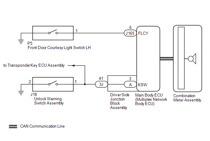
DESCRIPTION The key reminder warning buzzer sounds when the driver side door is opened while the ignition switch is in the LOCK or ACC position. The key reminder warning buzzer is activated when the main body ECU (multiplex network body ECU) sends a key switch signal and front door courtesy light switch LH signal to the combination meter assembly. WIRING DIAGRAM 
CAUTION / NOTICE / HINT NOTICE: The key reminder warning system uses the CAN communication system. Inspect the communication function by following How to Proceed with Troubleshooting. Troubleshoot the key reminder warning system after confirming that the communication systems are functioning properly. Click here PROCEDURE
(a) Check the seat belt warning buzzer function. Click here OK: The seat belt warning buzzer sounds properly.
(a) Open the driver door and check that the open door indicator on the combination meter assembly comes on. OK: Open door indicator comes on.
(a) Check that the security indicator on the combination meter assembly turns off, when the key is inserted into the ignition key cylinder. OK: Security indicator light turns off. HINT: When the security indicator turns off, the transponder key ECU assembly has detected the unlock warning switch signal.
(a) Connect the Techstream to the DLC3. (b) Turn the ignition switch to ON. (c) Turn the Techstream on. (d) Enter the following menus: Body Electrical / Main Body / Data List/ (e) According to the display on the Techstream, read on the Data List. Main Body
OK: On the Techstream screen, ON or OFF is displayed for each item according to the table above. HINT: The unlock warning switch is confirmed to be functioning normally, and therefore if the result is NG, the problem is in the harness between the unlock warning switch and the main body ECU (multiplex network body ECU).
(a) Disconnect the J18 unlock warning switch connector. (b) Remove the main body ECU (multiplex network body ECU) from the driver side junction block assembly. Click here (c) Measure the resistance according to the value(s) in the table below. Standard Resistance:
(b) Remove the main body ECU (multiplex network body ECU) from the driver side junction block assembly. Click here (c) Measure the resistance according to the value(s) in the table below. Standard Resistance:
|
Toyota Tundra Service Manual > Rear Brake: Disassembly
DISASSEMBLY PROCEDURE 1. REMOVE REAR DISC BRAKE BLEEDER PLUG CAP 2. REMOVE REAR DISC BRAKE BLEEDER PLUG 3. REMOVE CYLINDER BOOT (a) Using a screwdriver, remove the cylinder boot from the cylinder. HINT: Tape the screwdriver tip before use. 4. REMOVE REAR DISC BRAKE PISTON (a) Place a piece of cloth ...