DISASSEMBLY CAUTION / NOTICE / HINT HINT:
PROCEDURE 1. PRECAUTION NOTICE: After turning the ignition switch off, waiting time may be required before disconnecting
the cable from the battery terminal. Therefore, make sure to read the disconnecting
the cable from the battery terminal notice before proceeding with work (See page
2. DISCONNECT CABLE FROM NEGATIVE BATTERY TERMINAL CAUTION: Wait at least 90 seconds after disconnecting the cable from the negative (-) battery terminal to prevent airbag and seat belt pretensioner activation. 3. REMOVE REAR DOOR INSIDE HANDLE BEZEL PLUG LH
4. REMOVE REAR UPPER DOOR ARMREST BASE PANEL LH
5. REMOVE REAR POWER WINDOW REGULATOR SWITCH ASSEMBLY
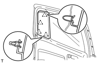
6. REMOVE REAR DOOR FRAME GARNISH LH
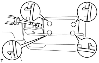
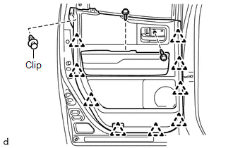
7. REMOVE REAR DOOR ARMREST COVER LH 8. REMOVE REAR DOOR TRIM BOARD SUB-ASSEMBLY LH
(b) Using a clip remover, remove the clip. (c) Detach the 9 clips and remove the trim cover. Then disconnect the connector.
9. REMOVE REAR INNER DOOR GLASS WEATHERSTRIP LH 10. REMOVE REAR NO. 2 DOOR TRIM BRACKET
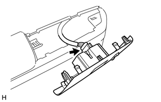
11. REMOVE REAR SPEAKER ASSEMBLY
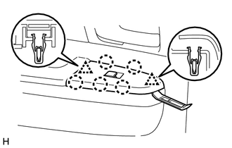
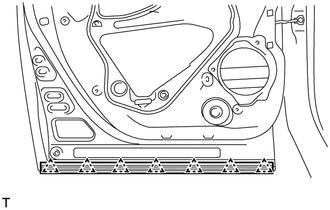
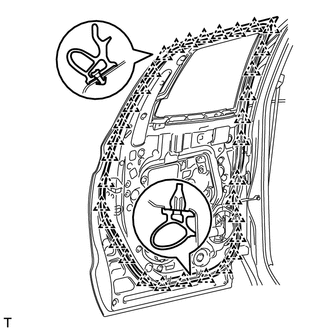
12. REMOVE REAR DOOR SERVICE HOLE COVER LH
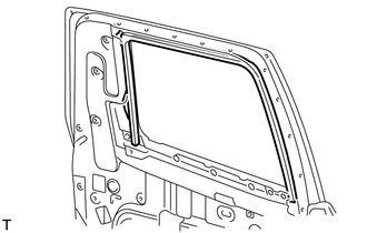
(b) Remove the rear door service hole cover. HINT: Remove the remaining tape on the door. 13. REMOVE REAR DOOR GLASS RUN LH
14. REMOVE REAR DOOR REAR LOWER WINDOW FRAME SUB-ASSEMBLY LH
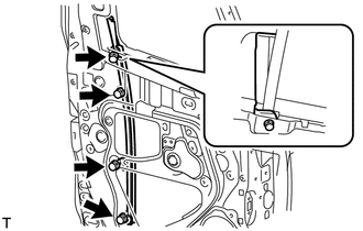
15. REMOVE REAR NO. 2 DOOR GLASS RUN LH (a) Remove the rear door glass run from the rear rear door lower window frame. 16. REMOVE REAR DOOR GLASS SUB-ASSEMBLY LH 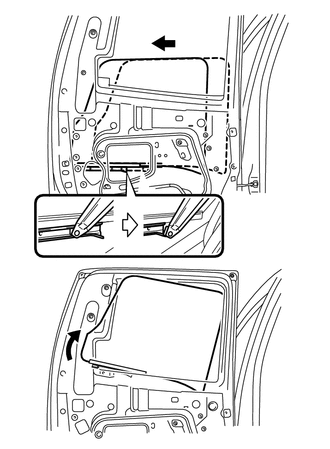
(a) Remove the rear door glass from the rear door window regulator as shown in the illustration. NOTICE: Do not damage the door glass. 17. REMOVE REAR DOOR FRONT WINDOW GUIDE SUB-ASSEMBLY LH
18. REMOVE REAR NO. 2 DOOR GLASS RUN LH (a) Remove the rear door glass run from the window frame front lower. 19. REMOVE REAR OUTER DOOR GLASS WEATHERSTRIP
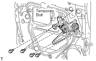
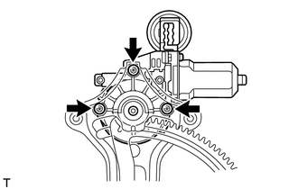
20. REMOVE REAR DOOR WINDOW REGULATOR SUB-ASSEMBLY LH
(b) Loosen the temporary bolt. NOTICE: Do not remove the temporary bolt. If the temporary bolt is removed, the front door window regulator may fall and become damaged. (c) Remove the 3 bolts and window regulator. (d) Remove the window regulator through the service hole. (e) Remove the temporary bolt from the door window regulator. 21. REMOVE POWER WINDOW REGULATOR MOTOR ASSEMBLY LH
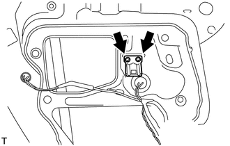
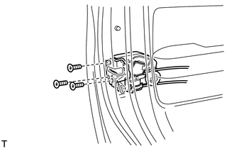
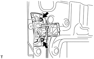
22. REMOVE REAR DOOR LOCK ASSEMBLY LH
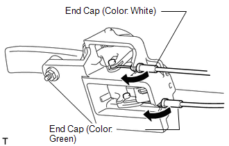
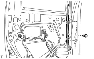
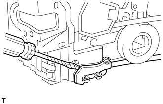
(b) Using a T30 "TORX" wrench, remove the 3 screws and door lock. HINT: Remove the door lock through the service hole. NOTICE: Be careful when removing the bolts as the door lock may fall and become damaged. 23. REMOVE REAR DOOR LOCK REMOTE CONTROL CABLE ASSEMBLY LH
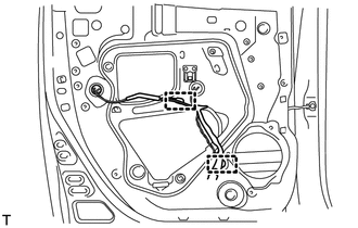
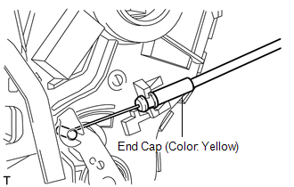
24. REMOVE REAR DOOR INSIDE LOCKING CABLE ASSEMBLY LH
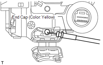
25. REMOVE REAR DOOR LOCK CHILD PROTECTION COVER LH 26. REMOVE REAR DOOR OUTSIDE HANDLE ASSEMBLY LH
27. REMOVE REAR DOOR LOCK OPEN ROD LH 28. REMOVE REAR NO. 2 DOOR WEATHERSTRIP LH
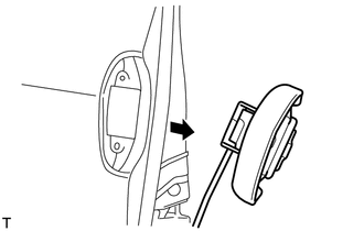
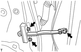
29. REMOVE REAR DOOR CHECK ASSEMBLY LH
30. REMOVE REAR DOOR WEATHERSTRIP LH
|
Toyota Tundra Service Manual > Audio And Visual System: Dtc Check / Clear
DTC CHECK / CLEAR 1. START DIAGNOSTIC MODE HINT: Illustrations may differ from the actual vehicle screen depending on the device settings and options. Therefore, some detailed areas may not be shown exactly the same as on the actual vehicle screen. If the system cannot enter the diagnostic mode, rep ...