DISASSEMBLY PROCEDURE 1. REMOVE REAR BUMPER PLATE LH
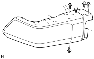
2. REMOVE REAR BUMPER PLATE RH HINT: Use the same procedure described for the LH side. 3. REMOVE REAR BUMPER PAD SUB-ASSEMBLY LH
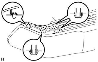
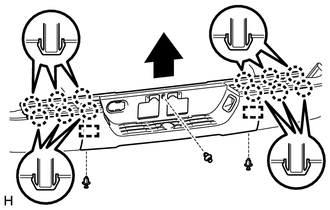
(b) Detach the 12 claws and 2 guides and remove the rear bumper pad sub-assembly LH as shown in the illustration. 4. REMOVE LICENSE PLATE LIGHT ASSEMBLY LH
5. REMOVE LICENSE PLATE LIGHT ASSEMBLY RH HINT: Use the same procedure described for the LH side. 6. REMOVE REAR BUMPER BAR CORNER REINFORCEMENT LH
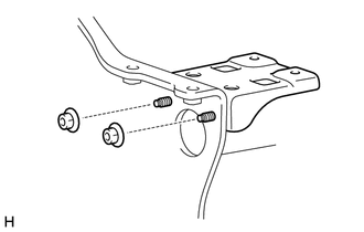
7. REMOVE REAR BUMPER BAR CORNER REINFORCEMENT RH HINT: Use the same procedure described for the LH side. 8. REMOVE NO. 2 ULTRASONIC SENSOR (w/ Intuitive Parking Assist System)
9. REMOVE NO. 2 ULTRASONIC SENSOR RETAINER (w/ Intuitive Parking Assist System)
10. REMOVE NO. 3 ULTRASONIC SENSOR (w/ Intuitive Parking Assist System)
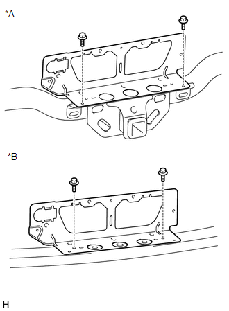
11. REMOVE NO. 2 FRAME WIRE (a) w/ Towing Package: (1) Detach all the clamps and remove the No. 2 frame wire from the receiver hitch bracket sub-assembly. 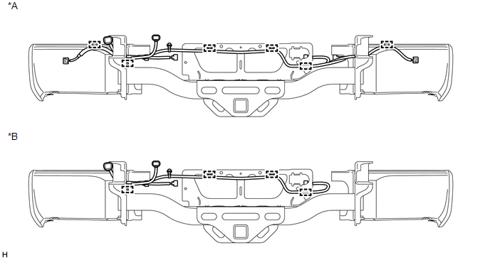 Text in Illustration Text in Illustration
(b) w/o Towing Package: (1) Detach all the clamps and remove the No. 2 frame wire from the rear bumper reinforcement sub-assembly. 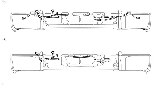 Text in Illustration Text in Illustration
12. REMOVE REAR BUMPER PLATE
13. REMOVE REAR BUMPER BAR LH
14. REMOVE REAR BUMPER BAR RH HINT: Use the same procedure described for the LH side. 15. REMOVE REAR BUMPER UPPER COVER LH
16. REMOVE REAR BUMPER UPPER COVER RH HINT: Use the same procedure described for the LH side. |
Toyota Tundra Service Manual > Rear Door Speaker(for Crewmax): Removal
REMOVAL CAUTION / NOTICE / HINT HINT: Use the same procedure for the RH and LH sides. The procedure listed below is for the LH side. PROCEDURE 1. REMOVE REAR DOOR FRAME GARNISH LH 2. REMOVE REAR DOOR INSIDE HANDLE BEZEL PLUG LH 3. REMOVE REAR UPPER DOOR ARMREST BASE PANEL LH 4. REMOVE REAR DOOR ARMR ...