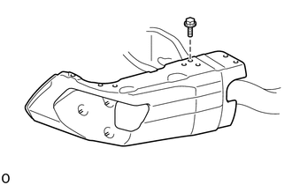
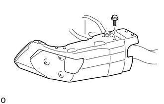
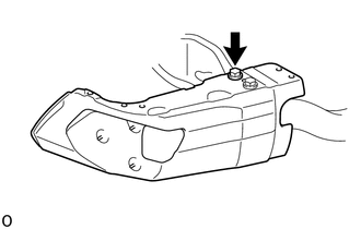
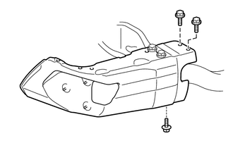
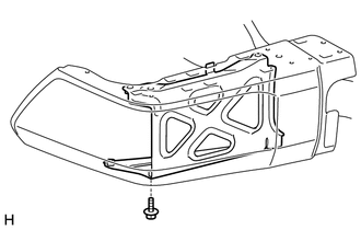
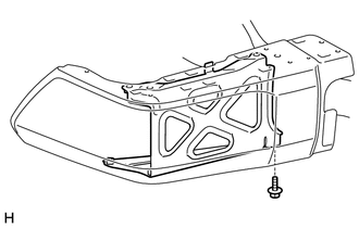
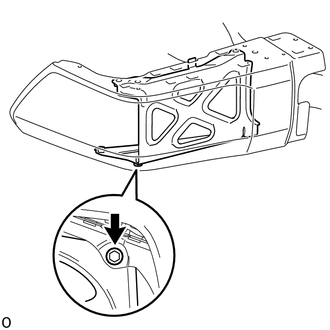
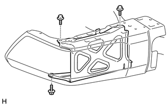
REASSEMBLY PROCEDURE 1. INSTALL REAR BUMPER UPPER COVER LH (a) Install the rear bumper upper cover LH with the 2 nuts. Torque: 30 N·m {306 kgf·cm, 22 ft·lbf} 2. INSTALL REAR BUMPER UPPER COVER RH HINT: Use the same procedure described for the LH side. 3. INSTALL REAR BUMPER PLATE (a) Install the rear bumper plate with the 2 bolts. Torque: 30 N·m {306 kgf·cm, 22 ft·lbf} 4. INSTALL REAR BUMPER SIDE STAY LH
5. INSTALL REAR BUMPER SIDE STAY RH HINT: Use the same procedure described for the LH side. 6. INSTALL NO. 2 FRAME WIRE (a) w/ Towing Package: (1) Attach all the clamps to install the No. 2 frame wire to the receiver hitch bracket sub-assembly. 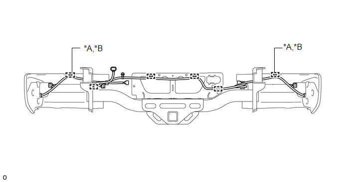
(b) w/o Towing Package: (1) Attach all the clamps to install the No. 2 frame wire to the rear bumper reinforcement sub-assembly. 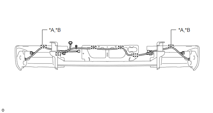
7. INSTALL NO. 3 ULTRASONIC SENSOR (w/ Intuitive Parking Assist System)
8. INSTALL NO. 2 ULTRASONIC SENSOR (w/ Intuitive Parking Assist System)
9. INSTALL BLIND SPOT MONITOR SENSOR LH (w/ Blind Spot Monitor System)
10. INSTALL BLIND SPOT MONITOR SENSOR RH (w/ Blind Spot Monitor System) HINT: Use the same procedure described for the LH side. 11. INSTALL REAR BUMPER BAR CORNER REINFORCEMENT LH
12. INSTALL REAR BUMPER BAR CORNER REINFORCEMENT RH HINT: Use the same procedure described for the LH side. 13. INSTALL REAR BUMPER EXTENSION INSERT LH (a) Install the rear bumper extension insert LH with the 8 clips. 14. INSTALL REAR BUMPER EXTENSION INSERT RH HINT: Use the same procedure described for the LH side. 15. INSTALL REAR BUMPER PAD SUB-ASSEMBLY LH (a) Attach the clamp to the No. 2 frame wire. (b) Attach the 12 claws and 2 guides to install a new rear bumper pad sub-assembly LH. (c) Install the 3 clips. 16. INSTALL REAR BUMPER PLATE LH (a) Attach the 3 claws and clip to install a new rear bumper plate LH. 17. INSTALL REAR BUMPER PLATE RH HINT: Use the same procedure described for the LH side. 18. INSTALL LICENSE PLATE LIGHT ASSEMBLY LH
19. INSTALL LICENSE PLATE LIGHT ASSEMBLY RH HINT: Use the same procedure described for the LH side. |
Toyota Tundra Service Manual > Tire And Wheel System: Inspection
INSPECTION PROCEDURE 1. INSPECT TIRE (a) Check the tires for wear and proper inflation pressure. Standard cold tire inflation pressure: Tire size Front kPa (kgf/cm2, psi) Rear kPa (kgf/cm2, psi) P255/70R18 210 (2.1, 30) 230 (2.3, 33) P275/65R18 P275/55R20 P255/70R18 (Spare Tire) P275/65R18 (Spare Ti ...