INSTALLATION CAUTION / NOTICE / HINT HINT: A bolt without a torque specification is shown in the standard bolt chart (See
page PROCEDURE 1. INSTALL NO. 1 INSTRUMENT PANEL CLIP
2. INSTALL NO. 3 INSTRUMENT PANEL STAY
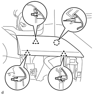
3. INSTALL INSTRUMENT PANEL SUB-ASSEMBLY (a) Set the instrument panel sub-assembly and attach the 5 claws. (b) Install the 2 nuts <C> and 3 bolts <B>. (c) Install the 2 bolts <G>. Torque: 20 N·m {204 kgf·cm, 15 ft·lbf} 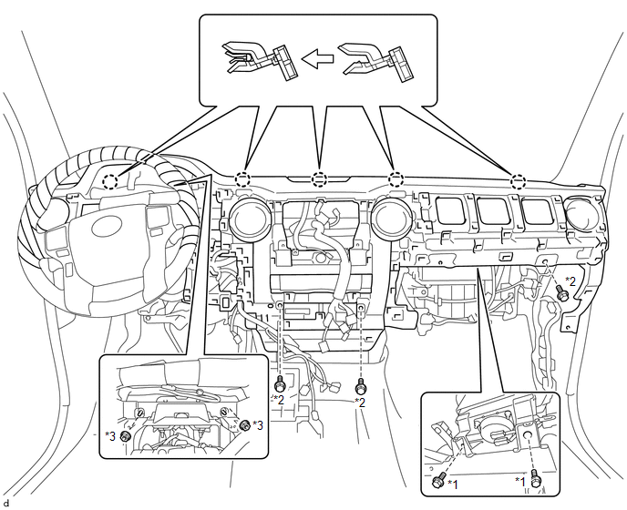 Text in Illustration Text in Illustration
(d) for Automatic Air Conditioning System: Attach the 2 claws to connect the cooler thermistor. (e) Connect each connector and attach each wire harness clamp. 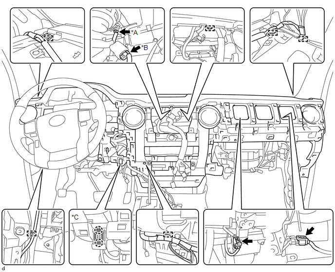 Text in Illustration Text in Illustration
4. INSTALL FRONT NO. 2 SPEAKER ASSEMBLY LH
5. INSTALL INSTRUMENT PANEL SPEAKER PANEL SUB-ASSEMBLY
6. INSTALL FRONT NO. 2 SPEAKER ASSEMBLY RH
7. INSTALL NO. 2 INSTRUMENT PANEL SPEAKER PANEL SUB-ASSEMBLY
8. INSTALL FRONT PILLAR GARNISH LH
9. INSTALL FRONT DOOR OPENING TRIM WEATHERSTRIP LH
10. INSTALL FRONT PILLAR GARNISH RH
11. INSTALL FRONT DOOR OPENING TRIM WEATHERSTRIP RH HINT: Use the same procedure described for the LH side. 12. INSTALL CENTER INSTRUMENT CLUSTER FINISH PANEL SUB-ASSEMBLY
13. INSTALL RADIO AND DISPLAY RECEIVER ASSEMBLY WITH BRACKET
14. INSTALL LOWER CENTER INSTRUMENT PANEL FINISH PANEL WITH AIR CONDITIONING CONTROL ASSEMBLY
15. INSTALL NO. 2 INSTRUMENT CLUSTER FINISH PANEL GARNISH
16. INSTALL LOWER INSTRUMENT PANEL FINISH PANEL SUB-ASSEMBLY RH
17. INSTALL INSTRUMENT SIDE PANEL RH
18. INSTALL NO. 4 INSTRUMENT REGISTER SUB-ASSEMBLY
19. INSTALL LOWER NO. 2 INSTRUMENT PANEL AIRBAG ASSEMBLY
20. INSTALL LOWER INSTRUMENT PANEL
21. INSTALL NO. 2 INSTRUMENT PANEL UNDER COVER SUB-ASSEMBLY
22. INSTALL COMBINATION METER ASSEMBLY
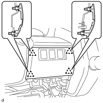
23. INSTALL INSTRUMENT CLUSTER FINISH PANEL ASSEMBLY (a) Attach the 6 clips to install the instrument cluster finish panel assembly. (b) Install the 2 clips. 24. INSTALL INSTRUMENT CLUSTER FINISH PANEL ORNAMENT
25. INSTALL NO. 2 SWITCH HOLE BASE (a) Connect each connector.
26. INSTALL NO. 1 INSTRUMENT CLUSTER FINISH PANEL GARNISH
27. INSTALL LOWER NO. 1 INSTRUMENT PANEL AIRBAG ASSEMBLY
28. INSTALL LOWER INSTRUMENT PANEL FINISH PANEL SUB-ASSEMBLY LH
29. INSTALL COWL SIDE TRIM BOARD LH
30. INSTALL FRONT DOOR SCUFF PLATE LH
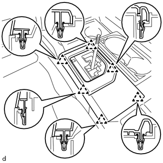
31. INSTALL COWL SIDE TRIM BOARD RH HINT: Use the same procedure described for the LH side. 32. INSTALL FRONT DOOR SCUFF PLATE RH HINT: Use the same procedure described for the LH side. 33. INSTALL FRONT CONSOLE BOX (a) Install the front console box with the 5 screws <E>. (b) Install the 2 clips and attach the connector. 34. INSTALL REAR CONSOLE BOX ASSEMBLY (a) Install the rear console box assembly with the 2 screws <E> and 4 bolts <B>. (b) Connect the 2 connectors. 35. INSTALL CONSOLE BOX CARPET (a) Install the console box carpet. 36. INSTALL REAR CONSOLE END PANEL SUB-ASSEMBLY (a) w/ Power Outlet Socket: Attach the 2 wire harness clamps and connect the connector.
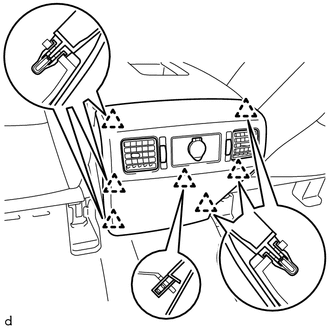
37. INSTALL UPPER CONSOLE PANEL SUB-ASSEMBLY (a) Attach the 12 clips to install the upper console panel sub-assembly. 38. INSTALL UPPER REAR CONSOLE PANEL SUB-ASSEMBLY
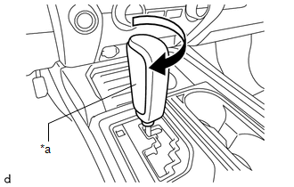
39. INSTALL SHIFT LEVER KNOB SUB-ASSEMBLY
40. INSTALL INSTRUMENT SIDE PANEL LH
41. INSTALL NO. 1 INSTRUMENT PANEL REGISTER SUB-ASSEMBLY
42. CONNECT CABLE TO NEGATIVE BATTERY TERMINAL NOTICE: When disconnecting the cable, some systems need to be initialized after the cable
is reconnected (See page 43. RESTORE AUTOAWAY/RETURN FUNCTION (for Power Tilt and Power Telescopic Steering Column) (a) Restore the Autoaway/Return function setting to the previous condition by
changing the customize parameter (See page 44. CHECK SRS WARNING LIGHT (See page |
Toyota Tundra Service Manual > Wiper / Washer: Washer Motor
Components COMPONENTS ILLUSTRATION Inspection INSPECTION PROCEDURE 1. INSPECT WINDSHIELD WASHER MOTOR AND PUMP ASSEMBLY HINT: This check should be performed with the windshield washer motor and pump installed to the washer jar. (a) Fill the washer jar with washer fluid. (b) Connect the battery's ...

 ).
).