Components COMPONENTS ILLUSTRATION 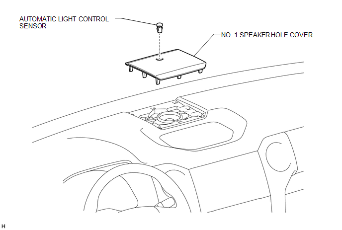
Installation INSTALLATION PROCEDURE 1. INSTALL AUTOMATIC LIGHT CONTROL SENSOR (a) Attach the 2 claws to install the automatic light control sensor. 2. INSTALL NO. 1 SPEAKER HOLE COVER (a) Connect the connector. (b) Attach the 8 clips to install the No. 1 speaker hole cover. On-vehicle Inspection ON-VEHICLE INSPECTION PROCEDURE 1. INSPECT AUTOMATIC LIGHT CONTROL SENSOR 
(a) Measure the voltage according to the value(s) in the table below. Standard Voltage:
(b) Measure the resistance according to the value(s) in the table below. Standard Resistance:
(c) Reconnect the automatic light control sensor connector.
Removal REMOVAL PROCEDURE 1. REMOVE NO. 1 SPEAKER HOLE COVER 
(a) Put protective tape around the No. 1 speaker hole cover. Text in Illustration
(b) Using moulding remover B, detach the 8 clips. (c) Disconnect the connector and remove the No. 1 speaker hole cover. 2. REMOVE AUTOMATIC LIGHT CONTROL SENSOR 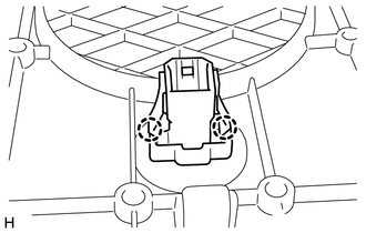
(a) Detach the 2 claws and remove the automatic light control sensor. |
Toyota Tundra Service Manual > Air Pump: Installation
INSTALLATION PROCEDURE 1. INSTALL AIR PUMP ASSEMBLY (a) Connect the 6 air pump insulators to the 2 air pump assemblies and install the 2 air pump assemblies to the air pump bracket. (b) Attach the 2 wire harness clamps to the air pump bracket. 2. INSTALL NO. 1 AIR INJECTION SYSTEM HOSE (a) Install t ...